
Arduino Nano Line Follower Robot with PID Control and Sensor Array
View and Edit Project In Cirkit Designer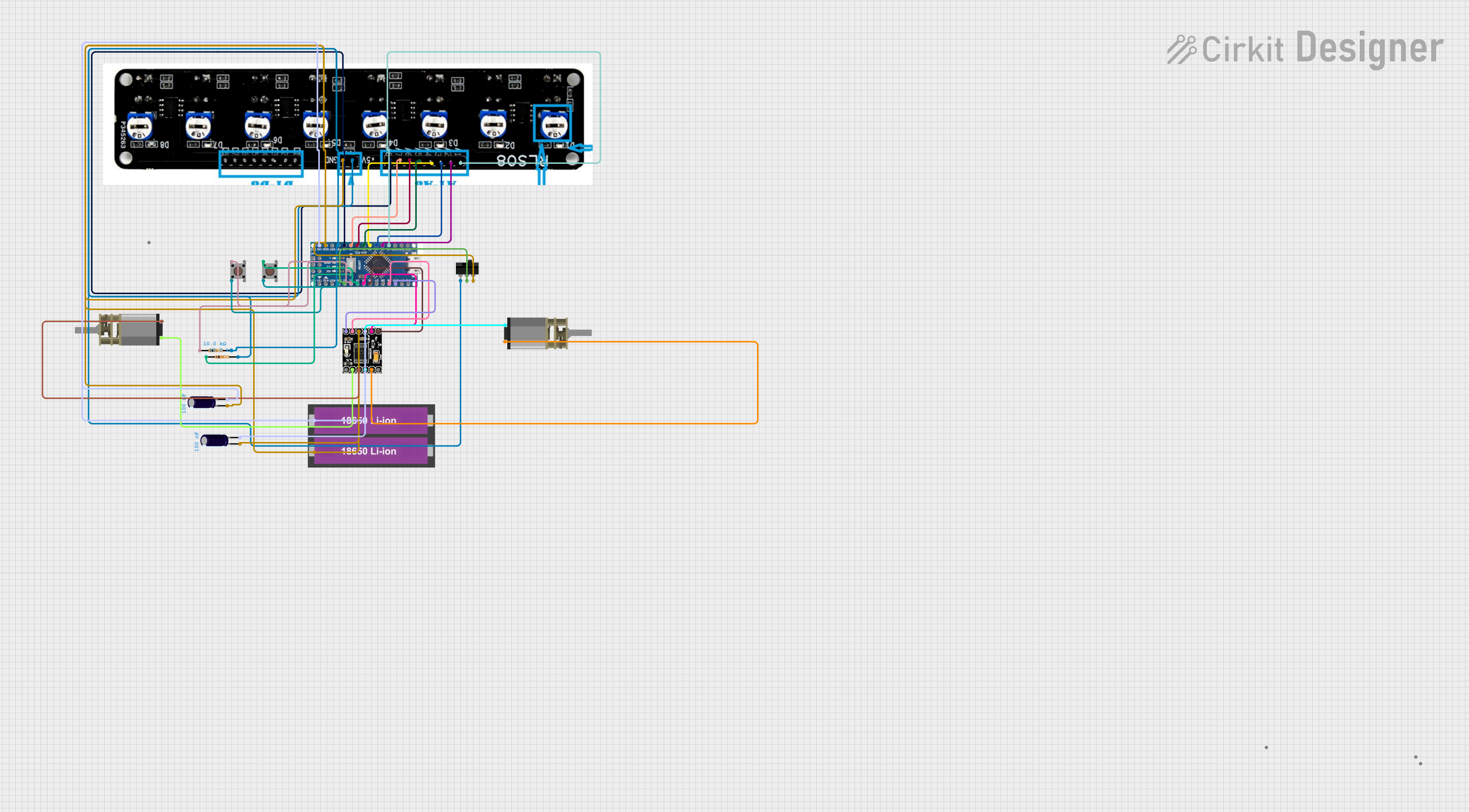
Circuit Documentation
Summary
This document provides a detailed overview of a line follower robot circuit. The circuit includes an Arduino Nano microcontroller, motor driver, DC motors, pushbuttons, a toggle switch, resistors, capacitors, a sensor array, and a battery pack. The robot uses PID control logic to follow a black line on a white surface, with calibration and start functionalities controlled by pushbuttons.
Component List
Arduino Nano
- Description: Microcontroller board based on the ATmega328P.
- Pins: D12, D11, D10, D9, D8, D7, D6, D5, D4, D3, D2, GND, D13, 3V3, AREF, A0, A1, A2, A3, A4 sda, A5 scl, A6, A7, 5V, RST, VIN, RX0, TX1, 13, 11, 12
Toggle Switch
- Description: A switch that toggles between two states.
- Pins: L1, COM, L2
Pushbutton
- Description: A momentary switch that makes or breaks a connection when pressed.
- Pins: Pin 3 (out), Pin 4 (out), Pin 1 (in), Pin 2 (in)
Resistor
- Description: A passive electrical component that provides resistance.
- Pins: pin1, pin2
- Properties: Resistance: 10,000 Ohms
Electrolytic Capacitor
- Description: A polarized capacitor with a larger capacitance per unit volume.
- Pins: -, +
- Properties: Capacitance: 100 nF
DC Mini Metal Gear Motor
- Description: A small DC motor with metal gears for increased torque.
- Pins: IN1, IN2
Drv8833
- Description: Dual H-Bridge motor driver IC.
- Pins: EEP, OUT1, OUT2, OUT3, OUT4, ULT, IN4, IN3, GND, VCC, IN1, IN2
18650 Li-ion Battery x 2
- Description: Rechargeable lithium-ion battery.
- Pins: +, -
Smartelex Sensor Array
- Description: Sensor array for line following.
- Pins: A1, A2, A3, A4, A5, A6, A7, A8, +5V, GND, D1, D2, D3, D4, D5, D6, D7, D8
Wiring Details
Arduino Nano
- D10 connected to Drv8833 IN4
- D9 connected to Drv8833 IN3
- D6 connected to Drv8833 IN2
- D5 connected to Drv8833 IN1
- D4 connected to Pushbutton Pin 1 (in) and Resistor pin1
- D3 connected to Pushbutton Pin 1 (in) and Resistor pin1
- D2 connected to Toggle Switch COM
- GND connected to Pushbutton Pin 2 (in), Pushbutton Pin 2 (in), Drv8833 GND, 18650 Li-ion Battery -, Smartelex Sensor Array GND, Toggle Switch L2
- A0 connected to Smartelex Sensor Array A1
- A1 connected to Smartelex Sensor Array A2
- A2 connected to Smartelex Sensor Array A3
- A3 connected to Smartelex Sensor Array A4
- A4 sda connected to Smartelex Sensor Array A5
- A5 scl connected to Smartelex Sensor Array A6
- A6 connected to Smartelex Sensor Array A7
- A7 connected to Smartelex Sensor Array A8
- 5V connected to Resistor pin2, Smartelex Sensor Array +5V, Toggle Switch L1
- VIN connected to Drv8833 VCC, 18650 Li-ion Battery +
Toggle Switch
- COM connected to Arduino Nano D2
- L1 connected to Arduino Nano 5V
- L2 connected to Arduino Nano GND
Pushbutton 1
- Pin 1 (in) connected to Arduino Nano D4 and Resistor pin1
- Pin 2 (in) connected to Arduino Nano GND
Pushbutton 2
- Pin 1 (in) connected to Arduino Nano D3 and Resistor pin1
- Pin 2 (in) connected to Arduino Nano GND
Resistor 1
- pin1 connected to Pushbutton Pin 1 (in) and Arduino Nano D4
- pin2 connected to Arduino Nano 5V
Resistor 2
- pin1 connected to Pushbutton Pin 1 (in) and Arduino Nano D3
- pin2 connected to Arduino Nano 5V
Electrolytic Capacitor 1
- - connected to Drv8833 GND
- + connected to Drv8833 VCC
Electrolytic Capacitor 2
- - connected to Drv8833 GND
- + connected to Drv8833 VCC
DC Mini Metal Gear Motor 1
- IN1 connected to Drv8833 OUT1
- IN2 connected to Drv8833 OUT2
DC Mini Metal Gear Motor 2
- IN1 connected to Drv8833 OUT3
- IN2 connected to Drv8833 OUT4
Drv8833
- OUT1 connected to DC Mini Metal Gear Motor IN1
- OUT2 connected to DC Mini Metal Gear Motor IN2
- OUT3 connected to DC Mini Metal Gear Motor IN1
- OUT4 connected to DC Mini Metal Gear Motor IN2
- IN4 connected to Arduino Nano D10
- IN3 connected to Arduino Nano D9
- IN2 connected to Arduino Nano D6
- IN1 connected to Arduino Nano D5
- GND connected to Arduino Nano GND
- VCC connected to Arduino Nano VIN
18650 Li-ion Battery x 2
- + connected to Arduino Nano VIN
- - connected to Arduino Nano GND
Smartelex Sensor Array
- A1 connected to Arduino Nano A0
- A2 connected to Arduino Nano A1
- A3 connected to Arduino Nano A2
- A4 connected to Arduino Nano A3
- A5 connected to Arduino Nano A4 sda
- A6 connected to Arduino Nano A5 scl
- A7 connected to Arduino Nano A6
- A8 connected to Arduino Nano A7
- +5V connected to Arduino Nano 5V
- GND connected to Arduino Nano GND
Code Documentation
Arduino Nano Code
/*
 * Line Follower Bot with PID Control
 * This code controls a line follower bot using PID logic for stability.
 * The bot starts when the toggle switch is on. The first button calibrates
 * the wheels, and the second button starts the line-following behavior.
 * The bot accurately follows a black line on a white surface, taking
 * precise turns at curves or edges.
 */

// Pin definitions
const int toggleSwitchPin = 2;
const int button1Pin = 3;
const int button2Pin = 4;
const int motor1Pin1 = 5;
const int motor1Pin2 = 6;
const int motor2Pin1 = 9;
const int motor2Pin2 = 10;
const int sensorPins[] = {A0, A1, A2, A3, A4, A5, A6, A7};

// PID constants
float Kp = 1.0;
float Ki = 0.0;
float Kd = 0.0;

// Variables for PID
float error = 0;
float previousError = 0;
float integral = 0;
float derivative = 0;

void setup() {
  // Initialize pins
  pinMode(toggleSwitchPin, INPUT);
  pinMode(button1Pin, INPUT);
  pinMode(button2Pin, INPUT);
  pinMode(motor1Pin1, OUTPUT);
  pinMode(motor1Pin2, OUTPUT);
  pinMode(motor2Pin1, OUTPUT);
  pinMode(motor2Pin2, OUTPUT);
  for (int i = 0; i < 8; i++) {
    pinMode(sensorPins[i], INPUT);
  }
}

void loop() {
  // Check if toggle switch is on
  if (digitalRead(toggleSwitchPin) ==