ESP32-Based Water Quality Monitoring System with I2C OLED Display and Wi-Fi Connectivity
Circuit Documentation
Summary
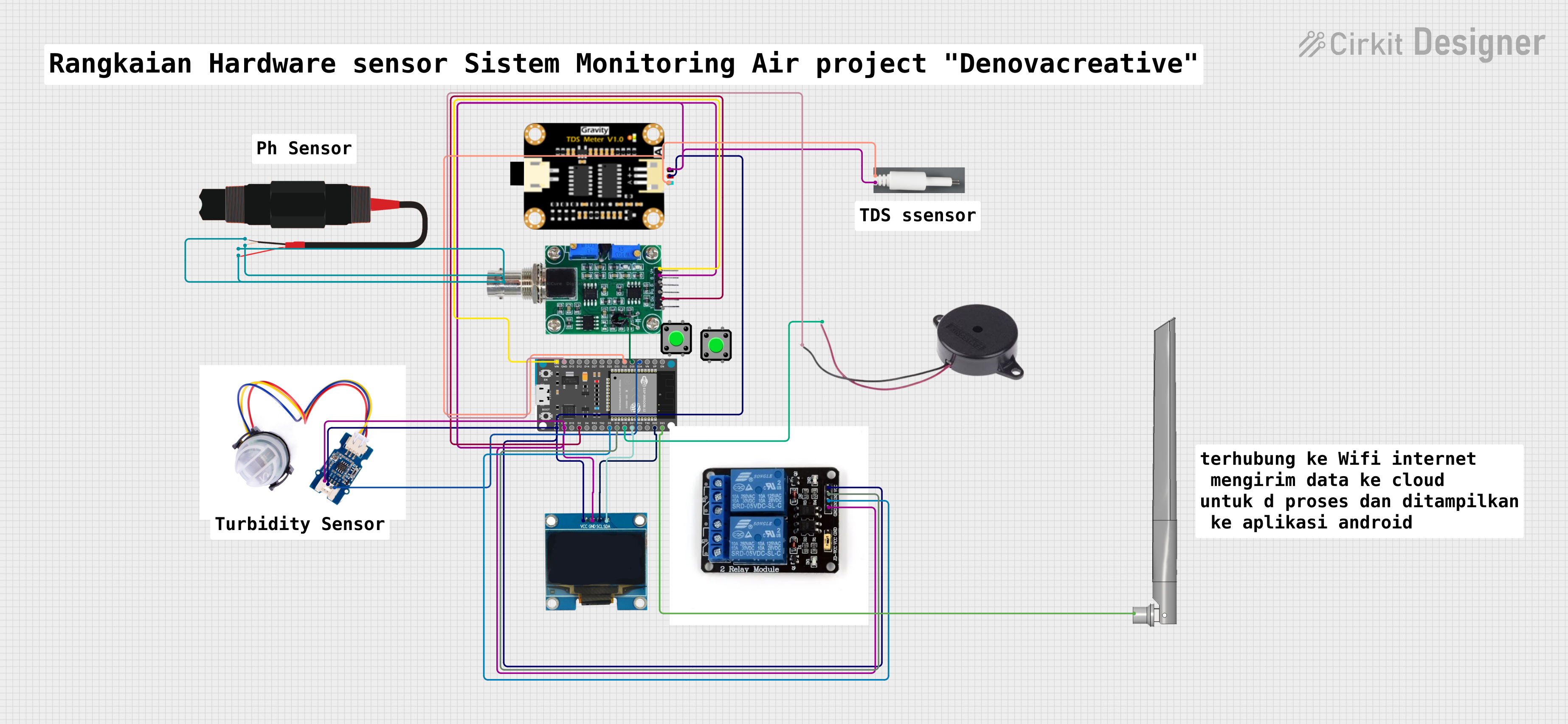
The circuit in question is designed to monitor various environmental parameters such as pH, turbidity, and total dissolved solids (TDS) levels. It utilizes an ESP32 Devkit V1 microcontroller as the central processing unit, interfacing with a pH sensor module, a turbidity sensor, a TDS sensor module, and an OLED screen for data display. The circuit also includes a two-channel relay module for controlling external devices, a buzzer for alerts, and a pushbutton for user input. The ESP32 is also connected to a WiFi antenna for potential wireless communication capabilities.
Component List
ESP32 Devkit V1
- Microcontroller with WiFi capabilities
- Pins: 3V3, GND, D15, D2, D4, RX2, TX2, D5, D18, D19, D21, RX0, TX0, D22, D23, EN, VP, VN, D34, D35, D32, D33, D25, D26, D27, D14, D12, D13, VIN
OLED Screen I2C
- Display screen for visual output
- Pins: Vcc, GND, SCL, SDA
pH Sensor Module by DM
- Sensor for measuring pH levels
- Pins: TO, DO, PO, GND, VCC, pH Electrode BNC interface, Temperature compensation
Two Channel Relay Module
- Module for controlling high power devices
- Pins: VCC, IN2, IN1, G, NO, C, NC
Buzzer
- Audio signaling device
- Pins: POSITIVE, NEGATIVE
Pushbutton (x2)
- User input device
- Pins: Pin 2, Pin 1, Pin 3, Pin 4
Turbidity Sensor Meter
- Sensor for measuring the cloudiness of a fluid
- Pins: GND, VCC, NC, SIG
TDS Sensor Module
- Sensor for measuring total dissolved solids in water
- Pins: TDS Negative, TDS Positive, TDS A
TDS Probe
- Probe for use with TDS Sensor Module
- Pins: A, B
PH Probe
- Probe for measuring pH levels
WiFi Antenna
- Antenna for enhancing WiFi signal
- Pins: SMA
Wiring Details
ESP32 Devkit V1
- 3V3: Power supply to OLED Screen, Two Channel Relay Module, TDS Sensor Module, Turbidity Sensor Meter
- GND: Common ground with OLED Screen, Two Channel Relay Module, TDS Sensor Module, Turbidity Sensor Meter, Buzzer
- D2: Digital output to pH Sensor Module (DO)
- D5: Digital output to Two Channel Relay Module (IN1)
- D18: Digital output to Two Channel Relay Module (IN2)
- D19: Digital output to Buzzer (POSITIVE)
- D21: I2C SDA to OLED Screen
- D22: I2C SCL to OLED Screen
- D23: Connection to WiFi Antenna (SMA)
- D34: Digital input from Turbidity Sensor Meter (SIG)
- D35: Digital input from pH Sensor Module (Temperature compensation)
- D32: Analog input from TDS Sensor Module (TDS A)
- VIN: Power supply to pH Sensor Module (VCC)
OLED Screen I2C
- Vcc: Power supply from ESP32 (3V3)
- GND: Common ground with ESP32
- SCL: I2C clock from ESP32 (D22)
- SDA: I2C data from ESP32 (D21)
pH Sensor Module by DM
- DO: Digital output to ESP32 (D2)
- GND: Common ground with ESP32
- VCC: Power supply from ESP32 (VIN)
- Temperature compensation: Analog input to ESP32 (D35)
- pH Electrode BNC interface: Connected to PH Probe
Two Channel Relay Module
- VCC: Power supply from ESP32 (3V3)
- IN1: Control signal from ESP32 (D5)
- IN2: Control signal from ESP32 (D18)
- G: Common ground with ESP32
Buzzer
- POSITIVE: Control signal from ESP32 (D19)
- NEGATIVE: Common ground with ESP32
Turbidity Sensor Meter
- VCC: Power supply from ESP32 (3V3)
- GND: Common ground with ESP32
- SIG: Analog signal to ESP32 (D34)
TDS Sensor Module
- TDS Positive: Power supply from ESP32 (3V3)
- TDS Negative: Common ground with ESP32
- TDS A: Analog signal to ESP32 (D32)
TDS Probe
- A: Connected to TDS Sensor Module (TDS A)
- B: Common ground with ESP32
Documented Code
Code for OLED Screen I2C (ESP32 Devkit V1)
#include <Wire.h>

void setup() {
  Wire.begin(21, 22); // Initialize I2C communication at pins 21 (SDA) and 22 (SCL)
  // Initialize OLED display here using the appropriate library and functions
}

void loop() {
  // Your code to update the OLED display
}
Filename: sketch.ino
Code for Turbidity Sensor Meter (ESP32 Devkit V1)
void setup() {
  // put your setup code here, to run once:

}

void loop() {
  // put your main code here, to run repeatedly:

}
Filename: sketch.ino
(Note: The code provided for the microcontrollers is minimal and would require further development to implement the functionality described in the summary. The code for the OLED screen initializes I2C communication, but does not include the library or functions necessary to operate the display. Similarly, the code for the turbidity sensor meter is a template without specific functionality.)