
Circuit Documentation
Summary
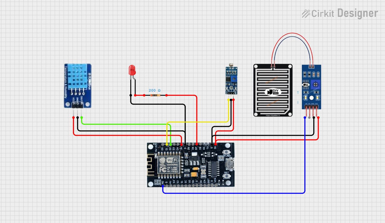
This circuit involves an ESP8266 microcontroller interfacing with various sensors and an LED. The sensors include a DHT11 temperature and humidity sensor, an LDR module for light detection, and a rain sensor. The LED is connected through a resistor. The ESP8266 provides the necessary power and control signals to these components.
Component List
ESP8266
- Description: A Wi-Fi enabled microcontroller used for IoT applications.
- Pins: 3V, G, D8, D7, D6, D5, D4, D3, D2, D1, D0, A0, S3, S2, S1, SC, S0, SK, EN, VIN, RST, VU
DHT11
- Description: A digital temperature and humidity sensor.
- Pins: DATA, GND, VCC
LED: Two Pin (red)
- Description: A red LED with two pins.
- Pins: cathode, anode
Resistor
- Description: A resistor with a resistance of 200 Ohms.
- Pins: pin1, pin2
- Properties: Resistance: 200 Ohms
LDR Module 3 pin
- Description: A light-dependent resistor module.
- Pins: VCC, GND, DO
RAIN SENSOR
- Description: A sensor module to detect rain.
- Pins: AO, DO, GRD, VCC
Wiring Details
ESP8266
- 3V: Connected to VCC of LDR Module, VCC of Rain Sensor, and VCC of DHT11.
- G: Connected to GND of LDR Module, GRD of Rain Sensor, and GND of DHT11. Also connected to the cathode of the LED.
- D7: Connected to pin2 of the Resistor.
- D2: Connected to DATA of DHT11.
- D1: Connected to DO of LDR Module.
- A0: Connected to AO of Rain Sensor.
DHT11
- GND: Connected to G of ESP8266.
- VCC: Connected to 3V of ESP8266.
- DATA: Connected to D2 of ESP8266.
LED: Two Pin (red)
- cathode: Connected to G of ESP8266.
- anode: Connected to pin1 of the Resistor.
Resistor
- pin1: Connected to anode of the LED.
- pin2: Connected to D7 of ESP8266.
LDR Module 3 pin
- VCC: Connected to 3V of ESP8266.
- GND: Connected to G of ESP8266.
- DO: Connected to D1 of ESP8266.
RAIN SENSOR
- AO: Connected to A0 of ESP8266.
- DO: Not connected.
- GRD: Connected to G of ESP8266.
- VCC: Connected to 3V of ESP8266.
Code
No code provided for this circuit.
This documentation provides a comprehensive overview of the circuit, including a summary, detailed component list, wiring details, and code section. Each component is described with its connections to ensure clarity and ease of understanding.