
ESP8266 NodeMCU with ADXL335 Accelerometer and Buzzer Alert System
View and Edit Project In Cirkit Designer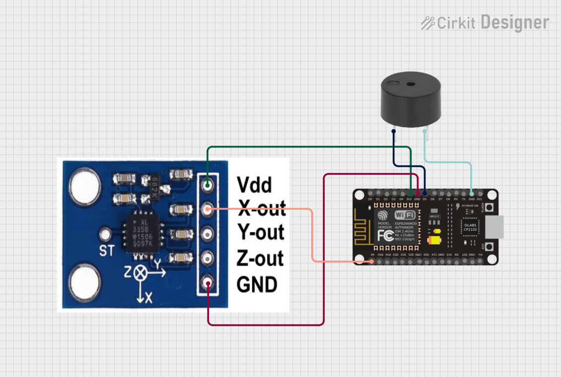
Circuit Documentation
Summary of the Circuit
This circuit is designed to interface an ADXXL335 accelerometer with an ESP8266 NodeMCU microcontroller. The accelerometer's data output for the X-axis is connected to the analog input of the ESP8266 for processing. Additionally, a buzzer is connected to one of the digital pins of the ESP8266 and is controlled through the microcontroller. The circuit is powered by the 3.3V supply from the ESP8266, which is common for both the accelerometer and the buzzer. Ground connections are shared across all components to complete the circuit.
Component List
ESP8266 NodeMCU
- Description: A Wi-Fi capable microcontroller module based on the ESP8266 chip.
- Pins: D0, D1, D2, D3, D4, 3V3, GND, D5, D6, D7, D8, RX, TX, A0, RSV, SD3, SD2, SD1, CMD, SD0, CLK, EN, RST, VIN
- Purpose: Acts as the central processing unit for the circuit, reads accelerometer data, controls the buzzer, and can communicate with other devices over Wi-Fi.
ADXXL335 Accelerometer
- Description: A small, thin, low power, complete 3-axis accelerometer with signal conditioned voltage outputs.
- Pins: VCC, X-OUT, Y-OUT, Z-OUT, GND
- Purpose: Measures acceleration along the X-axis and provides this data to the ESP8266 for analysis.
Buzzer
- Description: An electromechanical component that produces sound when an electrical signal is applied.
- Pins: PIN, GND
- Purpose: Provides an audible alert when triggered by the ESP8266.
Wiring Details
ESP8266 NodeMCU
- 3V3: Provides power to the ADXXL335 accelerometer (VCC pin) and the buzzer (PIN pin).
- GND: Connected to the ground (GND pin) of the ADXXL335 accelerometer and the buzzer to complete the power circuit.
- D5: Digital output connected to the PIN pin of the buzzer to control it.
- A0: Analog input connected to the X-OUT pin of the ADXXL335 accelerometer to read the X-axis acceleration data.
ADXXL335 Accelerometer
- VCC: Connected to the 3V3 pin of the ESP8266 NodeMCU for power.
- X-OUT: Output connected to the A0 pin of the ESP8266 NodeMCU to provide X-axis acceleration data.
- GND: Connected to the GND pin of the ESP8266 NodeMCU to complete the power circuit.
Buzzer
- PIN: Connected to the D5 pin of the ESP8266 NodeMCU to be controlled by the microcontroller.
- GND: Connected to the GND pin of the ESP8266 NodeMCU to complete the power circuit.
Documented Code
No code has been provided for the microcontrollers in the circuit. To fully utilize the circuit's capabilities, embedded code should be written and uploaded to the ESP8266 NodeMCU. The code should initialize the necessary pins, read the acceleration data from the ADXXL335 accelerometer, and control the buzzer based on specific conditions or thresholds.
Please note that the actual implementation of the code will depend on the specific requirements of the application and the logic that needs to be applied for the accelerometer data and buzzer control.