
Arduino Nano Controlled Robot with Ultrasonic Sensor and Dual Motor Drivers
View and Edit Project In Cirkit Designer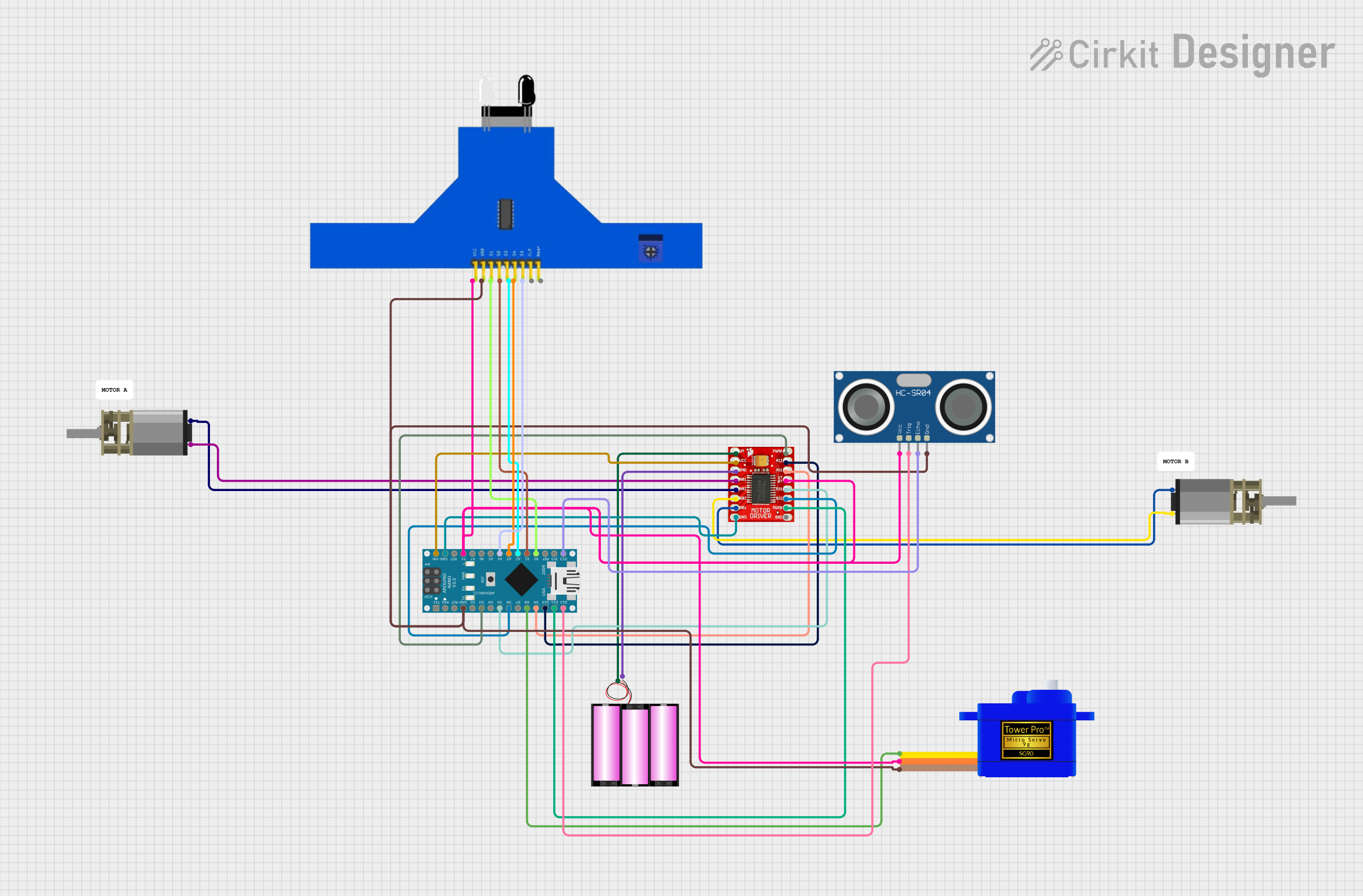
Circuit Documentation
Summary
This circuit is designed to control a pair of DC Mini Metal Gear Motors using a TB6612FNG Motor Driver, interfaced with an Arduino Nano microcontroller. The circuit also includes an HC-SR04 Ultrasonic Sensor for distance measurement, a Servomotor SG90 for positioning, and a 5 channel IR sensor for line or edge detection. Power is supplied by a 12V battery. The Arduino Nano is responsible for processing inputs from the sensors and controlling the motors and servomotor accordingly.
Component List
TB6612FNG Motor Driver
- Description: A motor driver capable of controlling two DC motors.
- Pins: GND, B01, B02, A02, A01, VCC, VM, PWMB, BI2, BI1, STBY, AI1, AI2, PWMA
HC-SR04 Ultrasonic Sensor
- Description: A sensor for measuring distance via ultrasonic waves.
- Pins: VCC, TRIG, ECHO, GND
Servomotor SG90
- Description: A small and lightweight servomotor for precise control.
- Pins: SIG, VCC, GND
Battery 12V
- Description: A 12V power source for the circuit.
- Pins: +, -
DC Mini Metal Gear Motor
- Description: A compact DC motor with a gearbox for increased torque.
- Pins: IN1, IN2
5 Channel IR Sensor
- Description: An array of IR sensors for line or edge detection.
- Pins: VCC, GND, S1, S2, S3, S4, S5, CLP, Near
Arduino Nano
- Description: A small, complete, and breadboard-friendly microcontroller board based on the ATmega328.
- Pins: D1/TX, D0/RX, RESET, GND, D2, D3, D4, D5, D6, D7, D8, D9, D10, D11/MOSI, D12/MISO, VIN, 5V, A7, A6, A5, A4, A3, A2, A1, A0, AREF, 3V3, D13/SCK
Wiring Details
TB6612FNG Motor Driver
- GND connected to Arduino Nano GND
- B01 connected to DC Mini Metal Gear Motor IN1
- B02 connected to DC Mini Metal Gear Motor IN2
- A02 connected to another DC Mini Metal Gear Motor IN2
- A01 connected to another DC Mini Metal Gear Motor IN1
- VCC connected to Arduino Nano VIN
- VM connected to Battery 12V +
- PWMB connected to Arduino Nano D11/MOSI
- BI2 connected to Arduino Nano D6
- BI1 connected to Arduino Nano D5
- STBY connected to multiple VCC lines (Arduino Nano 5V, Servomotor SG90 VCC, 5 channel IR sensor VCC, HC-SR04 Ultrasonic Sensor VCC)
- AI1 connected to Arduino Nano D9
- AI2 connected to Arduino Nano D10
- PWMA connected to Arduino Nano D3
HC-SR04 Ultrasonic Sensor
- VCC connected to Arduino Nano 5V
- TRIG connected to Arduino Nano D12/MISO
- ECHO connected to Arduino Nano D13/SCK
- GND connected to Arduino Nano GND
Servomotor SG90
- SIG connected to Arduino Nano D8
- VCC connected to Arduino Nano 5V
- GND connected to Arduino Nano GND
5 Channel IR Sensor
- VCC connected to Arduino Nano 5V
- GND connected to Arduino Nano GND
- S1 connected to Arduino Nano A0
- S2 connected to Arduino Nano A1
- S3 connected to Arduino Nano A2
- S4 connected to Arduino Nano A3
- S5 connected to Arduino Nano A4
Arduino Nano
- GND connected to common ground
- VIN connected to TB6612FNG Motor Driver VCC
- 5V connected to common VCC line
- D3, D5, D6, D8, D9, D10, D11/MOSI, D12/MISO, D13/SCK connected to respective components as detailed above
- A0, A1, A2, A3, A4 connected to 5 channel IR sensor S1, S2, S3, S4, S5 respectively
Documented Code
void setup() {
  // put your setup code here, to run once:

}

void loop() {
  // put your main code here, to run repeatedly:

}
Filename: sketch.ino
This is the basic template for the Arduino code. The setup() function is called once when the program starts and is used to initialize the settings. The loop() function runs continuously after setup() has finished. The actual implementation of the control logic for the motors, servomotor, and reading from the sensors will be added to this template.