
Circuit Documentation
Summary
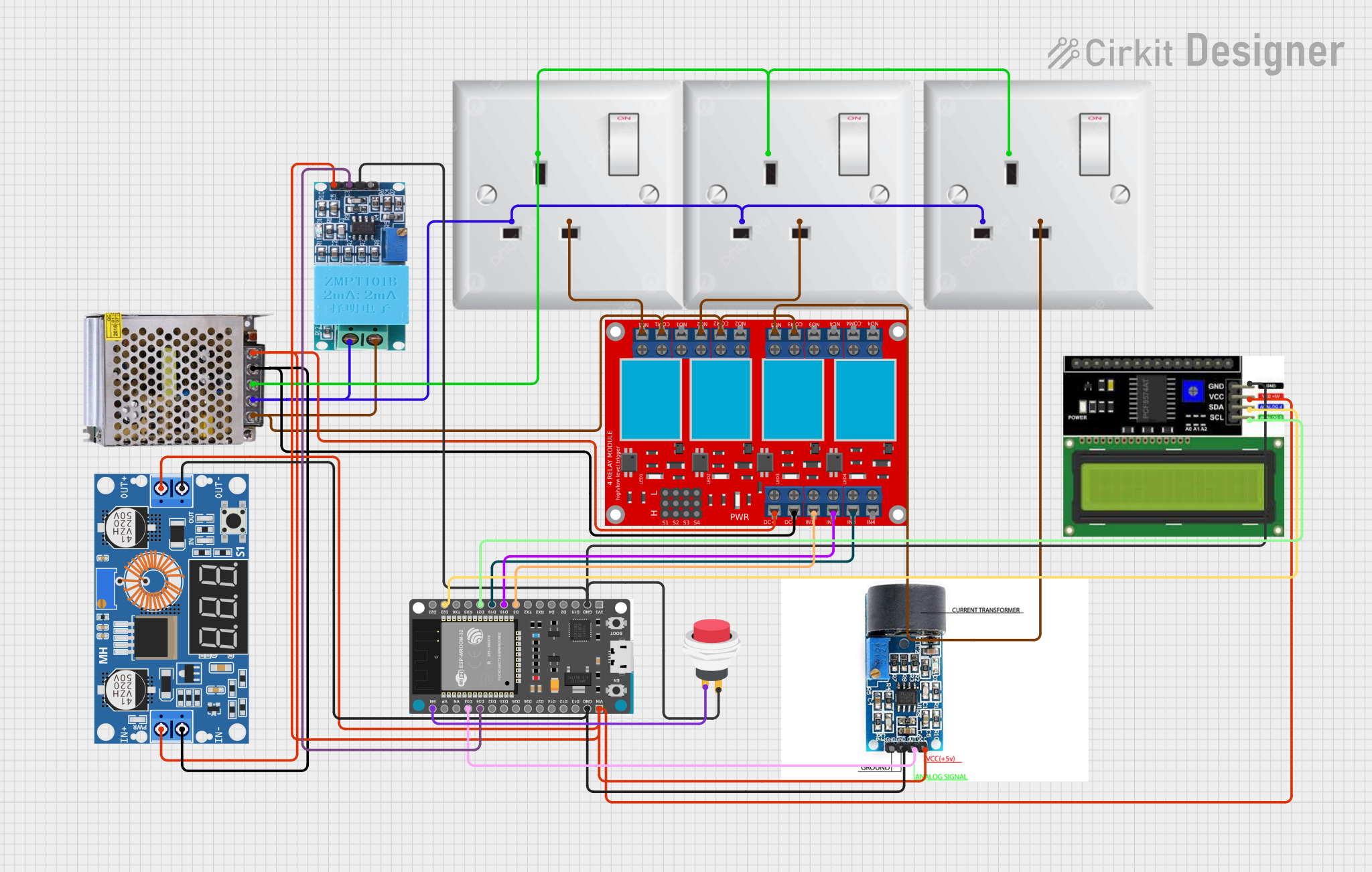
This circuit is designed to monitor AC current and voltage, control power to AC loads via a relay module, and display information on an LCD. It includes a microcontroller (ESP32 Devkit V1) for processing and control, current and voltage sensors (ZMCT103C and ZMPT101B), a DC power supply with a step-down converter (XL4015), and a user interface consisting of an LCD display and a push switch. The circuit is powered by a 12V 5A power supply, which is stepped down to 5V for the low-voltage components. The ESP32 reads analog signals from the sensors and controls the relay module based on the program logic, which is not provided in the code input.
Component List
- ZMCT103C CURRENT SENSOR: A current transformer that outputs an analog voltage proportional to the current passing through its sensing window.
- ZMPT101B: A module for measuring AC voltage, providing an analog output proportional to the voltage.
- XL4015 5A DC Buck Step-down: A DC-DC step-down (buck) converter module capable of stepping down voltages up to 5A.
- POWER SUPPLY 12V 5AMP: A power supply unit that provides a 12V 5A DC output from a 220V AC input.
- AC wall plug point: A standard AC wall plug point for connecting to the mains power supply.
- 4 channel relay module: A module with four relays, each capable of controlling an AC or DC load.
- LCD I2C Display: A liquid crystal display with an I2C interface for showing information.
- 2Pin Push Switch: A simple push-button switch for user input.
- ESP32 Devkit V1: A microcontroller with WiFi capabilities for controlling the circuit and processing sensor data.
Wiring Details
ZMCT103C CURRENT SENSOR
- VCC 5V: Connected to the 5V output from the step-down converter.
- ANALOG SIGNAL: Connected to pin D34 of the ESP32 for current measurement.
- GND: Connected to the ground plane of the circuit.
ZMPT101B
- OUT: Connected to pin D35 of the ESP32 for voltage measurement.
- GND: Connected to the ground plane of the circuit.
- VCC: Connected to the 5V output from the step-down converter.
- NEUTRO: Connected to the neutral line of the AC power supply.
- FASE: Connected to the phase line of the AC power supply through the relay module.
XL4015 5A DC Buck Step-down
- Output +: Connected to the 5V input of the ZMCT103C, ZMPT101B, LCD I2C Display, and ESP32.
- Output -: Connected to the ground plane of the circuit.
- Input +: Connected to the 12V-24V output from the power supply.
- Input -: Connected to the ground plane of the circuit.
POWER SUPPLY 12V 5AMP
- 220V Positive Pole (AC): Connected to the phase line of the AC wall plug point and the common (COM) terminals of the relay module.
- 220V Negative Pole (AC): Connected to the neutral line of the AC wall plug point.
- GND: Connected to the earth line of the AC wall plug point.
- GND (DC): Connected to the ground plane of the circuit.
- 12V-24V Output (DC): Connected to the input of the step-down converter and the VCC+ of the relay module.
AC wall plug point
- E: Earth connection, connected to the GND of the power supply.
- N: Neutral connection, connected to the 220V Negative Pole (AC) of the power supply and NEUTRO of ZMPT101B.
- L: Phase connection, connected to the 220V Positive Pole (AC) of the power supply and through the relay module to the FASE of ZMPT101B.
4 channel relay module
- N.O. x, COM x, N.C. x: Normally open, common, and normally closed terminals for relay channels x=1 to 4.
- VCC+: Connected to the 12V-24V output from the power supply.
- VCC- (GND): Connected to the ground plane of the circuit.
- IN x: Control inputs for relay channels x=1 to 4, connected to pins D5, D18, and D19 of the ESP32.
LCD I2C Display
- GND: Connected to the ground plane of the circuit.
- VCC: Connected to the 5V output from the step-down converter.
- SDA: Connected to pin D22 of the ESP32 for I2C data.
- SCL: Connected to pin D21 of the ESP32 for I2C clock.
2Pin Push Switch
- Input +: Connected to the EN pin of the ESP32 for reset functionality.
- Output +: Connected to the ground plane of the circuit.
ESP32 Devkit V1
- 3V3, GND, D15, D2, D4, RX2, TX2, D5, D18, D19, D21, RX0, TX0, D22, D23, EN, VP, VN, D34, D35, D32, D33, D25, D26, D27, D14, D12, D13, VIN: Various control and power pins, connected as described above.
Documented Code
The code for the ESP32 Devkit V1 microcontroller is not provided in the input. However, the expected functionality would include reading analog signals from the current and voltage sensors, controlling the relay module based on sensor readings or other logic, and displaying information on the LCD display. The code would also handle the push switch input for reset or other user interactions.
Without the actual code, we cannot provide a detailed documentation of the software part of the circuit. The code would typically be written in C or C++ using the Arduino IDE or the ESP-IDF framework and would include functions for initializing the hardware peripherals, reading sensor data, controlling the relays, and updating the display.