
ESP32-Based Smart Weather Station with Motorized Window Control
View and Edit Project In Cirkit Designer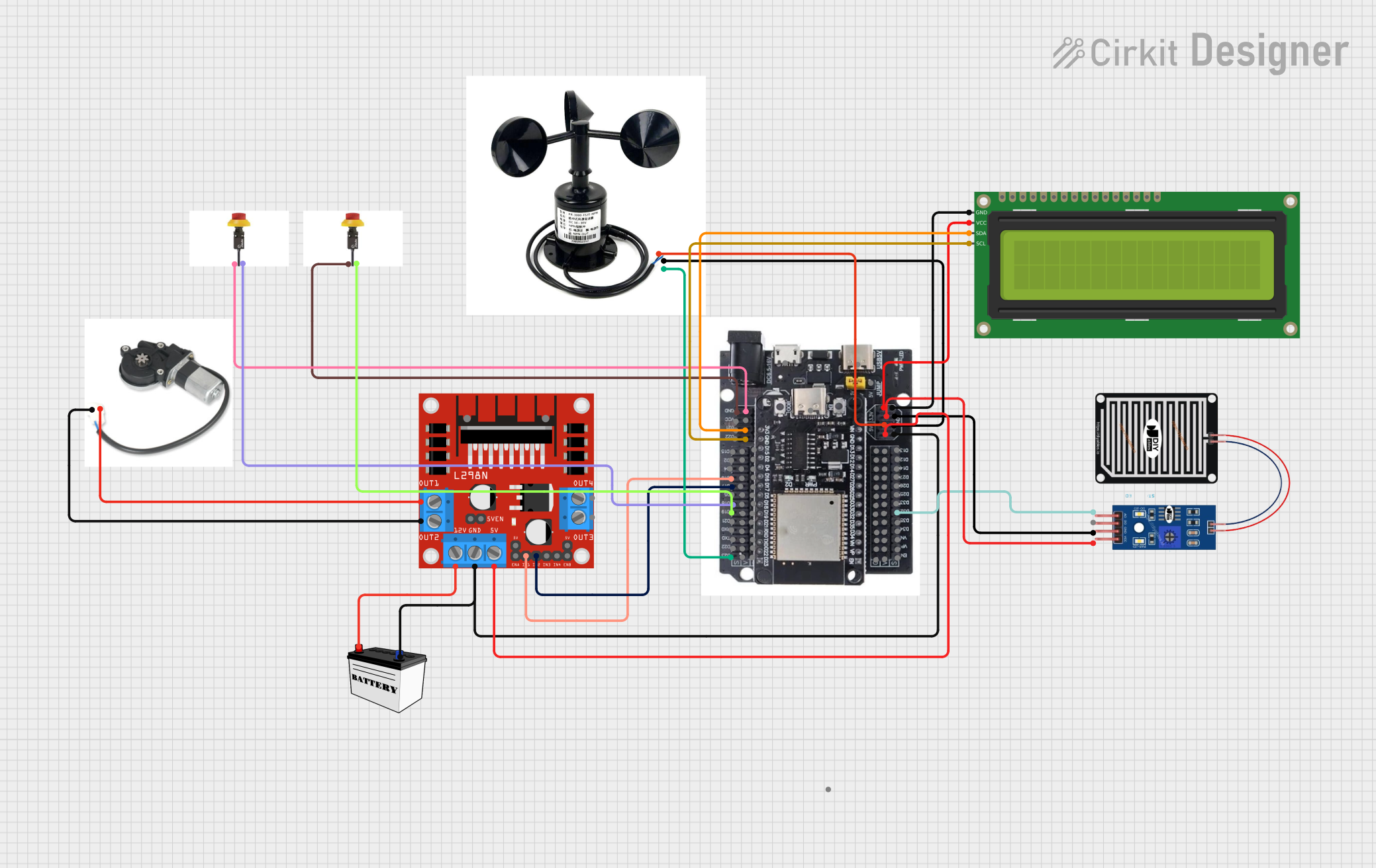
Circuit Documentation
Summary
This document provides a detailed overview of a circuit that includes an ESP32 Expansion Board, an Anemometer NPN, a L298N DC motor driver, a 12V Battery, a 16x2 I2C LCD, a Rain Sensor, Button Limit Switches, and a motor power window. The circuit is designed to interface various sensors and actuators with the ESP32 microcontroller for data acquisition and control.
Component List
Anemometer NPN
- Pins: VCC, GND, AO
- Description: Measures wind speed.
- Purpose in Circuit: Provides analog output proportional to wind speed.
ESP32 Expansion Board
- Pins: D13, D12, D14, D27, D26, D25, D33, D32, D34, VIN, VP, EN, 3.3V, Ground, D15, D2, D4, D16, D17, D5, D18, D19, D21, RX0, TX0, D22, D23, GND, VCC, D@@, Source, 5V
- Description: Microcontroller board with Wi-Fi and Bluetooth capabilities.
- Purpose in Circuit: Central control unit for data processing and communication.
L298N DC Motor Driver
- Pins: OUT1, OUT2, 12V, GND, 5V, OUT3, OUT4, 5V-ENA-JMP-I, 5V-ENA-JMP-O, +5V-J1, +5V-J2, ENA, IN1, IN2, IN3, IN4, ENB
- Description: Dual H-Bridge motor driver.
- Purpose in Circuit: Controls the motor power window.
12V Battery (Small Size)
- Pins: VCC, GND
- Description: Power source.
- Purpose in Circuit: Provides 12V power to the motor driver.
16x2 I2C LCD
- Pins: GND, VCC, SDA, SCL
- Description: Display module.
- Purpose in Circuit: Displays sensor data and system status.
Rain Sensor
- Pins: AO, DO, GRD, VCC
- Description: Detects rain.
- Purpose in Circuit: Provides analog output proportional to rain intensity.
Button Limit Switch
- Pins: -, +
- Description: Mechanical switch.
- Purpose in Circuit: Detects end positions of the motor power window.
Motor Power Window
- Pins: +, -
- Description: DC motor.
- Purpose in Circuit: Operates the power window.
Wiring Details
Anemometer NPN
- VCC connected to 5V of ESP32 Expansion Board
- GND connected to GND of ESP32 Expansion Board
- AO connected to D23 of ESP32 Expansion Board
ESP32 Expansion Board
- 5V connected to VCC of Anemometer NPN
- GND connected to GND of Anemometer NPN
- D23 connected to AO of Anemometer NPN
- D32 connected to AO of Rain Sensor
- D16 connected to IN1 of L298N DC Motor Driver
- D17 connected to IN2 of L298N DC Motor Driver
- D18 connected to + of Button Limit Switch
- D19 connected to + of Button Limit Switch
- GND connected to - of Button Limit Switch
- D21 connected to SDA of 16x2 I2C LCD
- D22 connected to SCL of 16x2 I2C LCD
- 5V connected to 5V of L298N DC Motor Driver
- GND connected to GND of L298N DC Motor Driver
- GND connected to GRD of Rain Sensor
- 3.3V connected to VCC of Rain Sensor
- GND connected to GND of 16x2 I2C LCD
- 3.3V connected to VCC of 16x2 I2C LCD
L298N DC Motor Driver
- IN1 connected to D16 of ESP32 Expansion Board
- IN2 connected to D17 of ESP32 Expansion Board
- 5V connected to 5V of ESP32 Expansion Board
- GND connected to GND of ESP32 Expansion Board
- GND connected to GND of 12V Battery
- OUT1 connected to + of Motor Power Window
- OUT2 connected to - of Motor Power Window
- 12V connected to VCC of 12V Battery
12V Battery (Small Size)
- VCC connected to 12V of L298N DC Motor Driver
- GND connected to GND of L298N DC Motor Driver
16x2 I2C LCD
- GND connected to GND of ESP32 Expansion Board
- VCC connected to 3.3V of ESP32 Expansion Board
- SDA connected to D21 of ESP32 Expansion Board
- SCL connected to D22 of ESP32 Expansion Board
Rain Sensor
- AO connected to D32 of ESP32 Expansion Board
- GRD connected to GND of ESP32 Expansion Board
- VCC connected to 3.3V of ESP32 Expansion Board
Button Limit Switch (Instance 1)
- + connected to D18 of ESP32 Expansion Board
- - connected to GND of ESP32 Expansion Board
Button Limit Switch (Instance 2)
- + connected to D19 of ESP32 Expansion Board
- - connected to GND of ESP32 Expansion Board
Motor Power Window
- + connected to OUT1 of L298N DC Motor Driver
- - connected to OUT2 of L298N DC Motor Driver
Code
No code provided for this circuit.
This document provides a comprehensive overview of the circuit, including a summary, component list, wiring details, and code section. Each component is described, and its connections are detailed to ensure clarity and ease of understanding.