
ESP8266 NodeMCU Controlled Ultrasonic Sensor with Alert System
View and Edit Project In Cirkit Designer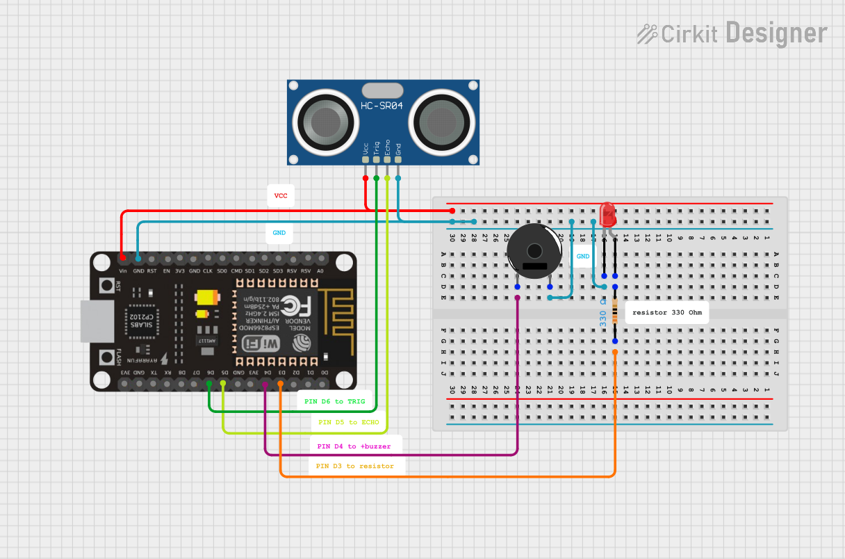
Circuit Documentation
Summary
The circuit in question is designed to interface an HC-SR04 Ultrasonic Sensor with an ESP8266 NodeMCU microcontroller. The ESP8266 NodeMCU is used to control the sensor and process its signals. Additionally, the circuit includes a resistor, an LED, and a piezo buzzer for indication purposes. The LED and buzzer are controlled by the ESP8266 NodeMCU to provide visual and audible feedback based on the sensor readings.
Component List
HC-SR04 Ultrasonic Sensor
- Description: A sensor that measures distance by emitting ultrasonic waves and measuring the time taken for the echo to return.
- Pins: VCC, TRIG, ECHO, GND
ESP8266 NodeMCU
- Description: A Wi-Fi enabled microcontroller that is capable of executing user-defined programs and interfacing with various sensors and actuators.
- Pins: D0, D1, D2, D3, D4, 3V3, GND, D5, D6, D7, D8, RX, TX, A0, RSV, SD3, SD2, SD1, CMD, SD0, CLK, EN, RST, VIN
Resistor
- Description: A passive two-terminal electrical component that implements electrical resistance as a circuit element.
- Properties: 330 Ohms
Piezo Buzzer
- Description: An electronic device that emits a tone when an electric current is passed through it.
- Pins: pin 1, pin 2
LED: Two Pin (red)
- Description: A red light-emitting diode that emits light when a current flows through it.
- Pins: cathode, anode
Wiring Details
HC-SR04 Ultrasonic Sensor
- VCC connected to ESP8266 NodeMCU VIN
- TRIG connected to ESP8266 NodeMCU D6
- ECHO connected to ESP8266 NodeMCU D5
- GND connected to common ground net
ESP8266 NodeMCU
- D3 connected to one end of the Resistor
- GND connected to common ground net
- VIN connected to HC-SR04 Ultrasonic Sensor VCC
- D6 connected to HC-SR04 Ultrasonic Sensor TRIG
- D5 connected to HC-SR04 Ultrasonic Sensor ECHO
- D4 connected to Piezo Buzzer pin 1
Resistor
- pin1 connected to ESP8266 NodeMCU D3
- pin2 connected to LED anode
Piezo Buzzer
- pin 1 connected to ESP8266 NodeMCU D4
- pin 2 connected to common ground net
LED: Two Pin (red)
- cathode connected to common ground net
- anode connected to one end of the Resistor
Documented Code
No code has been provided for the microcontroller. The documentation of the code would typically include a description of the functionality, setup, and main loop, along with comments explaining the purpose of each section of the code. Since no code is available, this section cannot be completed.