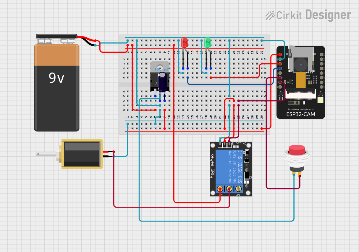
ESP32-CAM Based Smart Security System with Face Recognition

Smart Home Security System Circuit Documentation
Summary
The Smart Home Security System is designed around the ESP32-CAM microcontroller, which serves as the central processing unit capable of Wi-Fi communication, image capture, and face recognition. The system is equipped with a solenoid lock, voltage regulator, LEDs, a relay module, a push switch, and a 9V battery for power supply. The ESP32-CAM is programmed to interact with the Blynk platform for remote notifications and control. The system can detect a person's presence, capture their image, and use face recognition to determine if the person is known. If the person is recognized, the system can trigger actions such as unlocking a door.
Component List
- ESP32-CAM: A Wi-Fi and Bluetooth enabled microcontroller with an integrated camera for image capturing and processing capabilities.
- Solenoid: An electromechanical device used as a lock, which can be controlled to lock or unlock a door.
- Voltage Regulator (V_REG_LD1117VXX): A component that regulates the input voltage to a stable output voltage for the circuit.
- LEDs (Green and Red): Indicators for system status, such as access granted (green) or denied (red).
- 1-Channel Relay (5V 10A): An electrically operated switch that allows the ESP32-CAM to control higher power circuits like the solenoid lock.
- 9V Battery: The power source for the circuit.
- Electrolytic Capacitor: A component used to filter out voltage spikes and smooth the power supply.
- 2Pin Push Switch: A button that, when pressed, can trigger an action such as capturing an image.
Wiring Details
ESP32-CAM
- 5V to Voltage Regulator OUT
- GND to 9V Battery -, Solenoid pin1, LED (green) cathode, LED (red) cathode, Relay ground
- IO12 to LED (green) anode
- IO13 to LED (red) anode
- IO2 to Relay signal
- IO14 to Push Switch Output +
Solenoid
- pin1 to GND
- pin2 to Relay NO
Voltage Regulator (V_REG_LD1117VXX)
- GND to 9V Battery +
- OUT to ESP32-CAM 5V, Electrolytic Capacitor -, Push Switch Input +
- IN to 9V Battery -
LEDs
- Green LED
- cathode to GND
- anode to ESP32-CAM IO12
- Red LED
- cathode to GND
- anode to ESP32-CAM IO13
1-Channel Relay (5V 10A)
- NC not connected
- signal to ESP32-CAM IO2
- C to Solenoid pin2
- power to Electrolytic Capacitor +
- NO to GND
- ground to GND
9V Battery
- - to GND
- + to Voltage Regulator GND
Electrolytic Capacitor
- - to Voltage Regulator OUT
- + to Relay power
2Pin Push Switch
- Input + to Voltage Regulator OUT
- Output + to ESP32-CAM IO14
Documented Code
The embedded code for the ESP32-CAM microcontroller is written in C++ and is designed to work with the Blynk platform for IoT applications. The code includes libraries for Wi-Fi connectivity, camera functionality, and web server capabilities. It defines the camera model, initializes camera settings, and sets up a web server to stream video and capture images. The code also includes face recognition algorithms and functions to handle HTTP requests for capturing images, streaming video, and controlling the system remotely.
The code is organized into several files:
- CameraFaceRecognitionDoorLock.ino: The main program file that sets up the camera, connects to Wi-Fi, and starts the camera server. It includes functions to take photos, handle button presses, and send notifications via Blynk.
- camera_index.h: Contains the HTML web page served by the ESP32-CAM's web server for user interaction.
- camera_pins.h: Defines the GPIO pins used by the camera model.
- app_httpd.h: Contains the setup for the web server and the handlers for HTTP requests.
The system is designed to be modular, allowing for easy updates and maintenance. The code is well-documented, with comments explaining the functionality of each section and function.