Cirkit Designer
Your all-in-one circuit design IDE
Home /
Project Documentation
Arduino-Based Multiplexer-Controlled Servo and Photocell System with LCD Display
Circuit Documentation
Summary
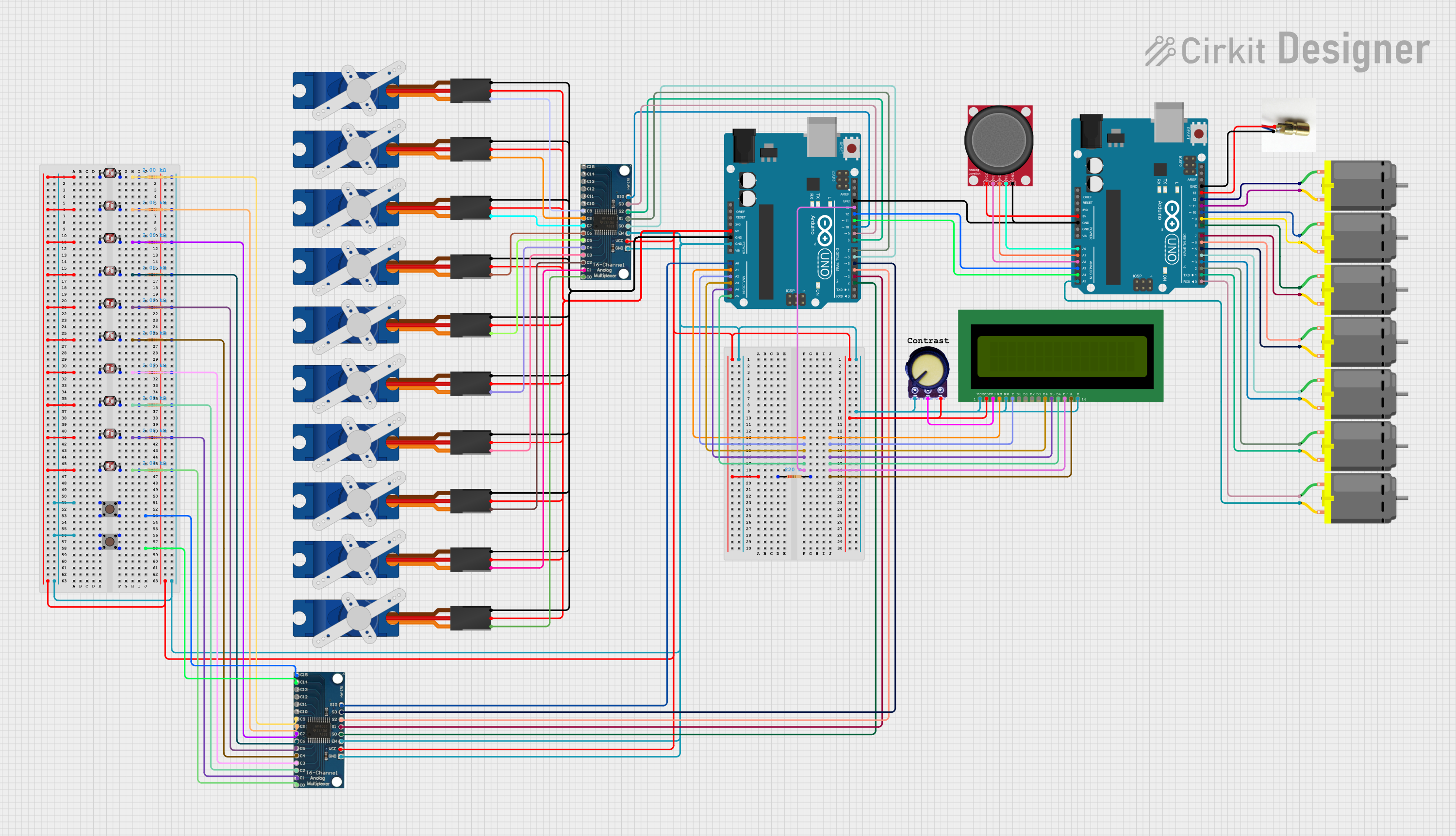
This circuit involves multiple components including two Arduino UNO microcontrollers, 16-channel analog multiplexers, Tower Pro SG90 servos, photocells (LDRs), resistors, a potentiometer, an LCD display, a laser diode, an analog joystick, and DC motors. The circuit is designed to interface various sensors and actuators with the Arduino microcontrollers, allowing for complex control and monitoring tasks.
Component List
16 Channel Analog Multiplexer
- Description: Analog multiplexer for selecting one of 16 input channels.
- Pins: GND, VCC, EN, S0, S1, S2, S3, SIG, C0-C15
Arduino UNO
- Description: Microcontroller board based on the ATmega328P.
- Pins: UNUSED, IOREF, Reset, 3.3V, 5V, GND, Vin, A0-A5, SCL, SDA, AREF, D0-D13
Tower Pro SG90 Servo
- Description: Small servo motor for precise control of angular position.
- Pins: Signal, +5V, GND
Photocell (LDR)
- Description: Light-dependent resistor for measuring light intensity.
- Pins: pin 0, pin 1
Resistor
- Description: Passive electrical component to limit current.
- Pins: pin1, pin2
- Properties: Resistance: 2000 Ohms
Potentiometer
- Description: Variable resistor for adjusting voltage.
- Pins: GND, Output, VCC
LCD 16x2 (Wokwi Compatible)
- Description: 16x2 character LCD display.
- Pins: VSS, VDD, V0, RS, RW, E, D0-D7, A, K
Laser Diode
- Description: Diode that emits laser light.
- Pins: negative, positive
Analog Joystick (Wokwi Compatible)
- Description: Joystick for analog input.
- Pins: VCC, VERT, HORZ, SEL, GND
DC Motor
- Description: Motor for rotational motion.
- Pins: pin 1, pin 2
Pushbutton
- Description: Simple pushbutton switch.
- Pins: Pin 1 (in), Pin 2 (in), Pin 3 (out), Pin 4 (out)
Wiring Details
16 Channel Analog Multiplexer
- VCC: Connected to Arduino UNO 5V
- GND: Connected to Arduino UNO GND
- EN: Connected to Arduino UNO GND
- S0: Connected to Arduino UNO D2
- S1: Connected to Arduino UNO D3
- S2: Connected to Arduino UNO D4
- S3: Connected to Arduino UNO D5
- SIG: Connected to Arduino UNO A0
- C0: Connected to Photocell (LDR) pin 1 through a 2000 Ohm resistor
- C1: Connected to Photocell (LDR) pin 1 through a 2000 Ohm resistor
- C2: Connected to Photocell (LDR) pin 1 through a 2000 Ohm resistor
- C3: Connected to Photocell (LDR) pin 1 through a 2000 Ohm resistor
- C4: Connected to Photocell (LDR) pin 1 through a 2000 Ohm resistor
- C5: Connected to Photocell (LDR) pin 1 through a 2000 Ohm resistor
- C6: Connected to Photocell (LDR) pin 1 through a 2000 Ohm resistor
- C7: Connected to Photocell (LDR) pin 1 through a 2000 Ohm resistor
- C8: Connected to Photocell (LDR) pin 1 through a 2000 Ohm resistor
- C9: Connected to Photocell (LDR) pin 1 through a 2000 Ohm resistor
- C10-C15: Not connected
Arduino UNO
- 5V: Connected to VCC of various components
- GND: Connected to GND of various components
- A0: Connected to SIG of 16 Channel Analog Multiplexer
- A1: Connected to RS of LCD 16x2
- A2: Connected to E of LCD 16x2
- A3: Connected to D4 of LCD 16x2
- A4: Connected to D5 of LCD 16x2
- A5: Connected to D6 of LCD 16x2
- D2: Connected to S0 of 16 Channel Analog Multiplexer
- D3: Connected to S1 of 16 Channel Analog Multiplexer
- D4: Connected to S2 of 16 Channel Analog Multiplexer
- D5: Connected to S3 of 16 Channel Analog Multiplexer
- D13: Connected to D7 of LCD 16x2
Tower Pro SG90 Servo
- Signal: Connected to C0-C9 of 16 Channel Analog Multiplexer
- +5V: Connected to Arduino UNO 5V
- GND: Connected to Arduino UNO GND
Photocell (LDR)
- pin 0: Connected to other LDR pin 0s
- pin 1: Connected to C0-C9 of 16 Channel Analog Multiplexer through a 2000 Ohm resistor
Resistor
- pin1: Connected to pin 1 of Photocell (LDR)
- pin2: Connected to GND
Potentiometer
- GND: Connected to GND
- Output: Connected to V0 of LCD 16x2
- VCC: Connected to 5V
LCD 16x2 (Wokwi Compatible)
- VSS: Connected to GND
- VDD: Connected to 5V
- V0: Connected to Output of Potentiometer
- RS: Connected to A1 of Arduino UNO
- RW: Connected to GND
- E: Connected to A2 of Arduino UNO
- D4: Connected to A3 of Arduino UNO
- D5: Connected to A4 of Arduino UNO
- D6: Connected to A5 of Arduino UNO
- D7: Connected to D13 of Arduino UNO
- A: Connected to 5V through a 220 Ohm resistor
- K: Connected to GND
Laser Diode
- negative: Connected to GND
- positive: Connected to D13 of Arduino UNO
Analog Joystick (Wokwi Compatible)
- VCC: Connected to 5V
- VERT: Connected to A2 of Arduino UNO
- HORZ: Connected to A1 of Arduino UNO
- SEL: Connected to A0 of Arduino UNO
- GND: Connected to GND
DC Motor
- pin 1: Connected to D0-D13 of Arduino UNO
- pin 2: Connected to D0-D13 of Arduino UNO
Pushbutton
- Pin 1 (in): Connected to C15 of 16 Channel Analog Multiplexer
- Pin 2 (in): Connected to C14 of 16 Channel Analog Multiplexer
- Pin 3 (out): Connected to GND
- Pin 4 (out): Connected to GND
Documented Code
Arduino UNO (Instance 1)
sketch.ino
void setup() {
  // put your setup code here, to run once:

}

void loop() {
  // put your main code here, to run repeatedly:

}
Arduino UNO (Instance 2)
sketch.ino
void setup() {
  // put your setup code here, to run once:

}

void loop() {
  // put your main code here, to run repeatedly:

}
This documentation provides a comprehensive overview of the circuit, including a detailed component list, wiring details, and the code used in the microcontrollers.