
MCP23017-Expanded I/O Interface with ADS1115 ADC and ESP32 Control
View and Edit Project In Cirkit Designer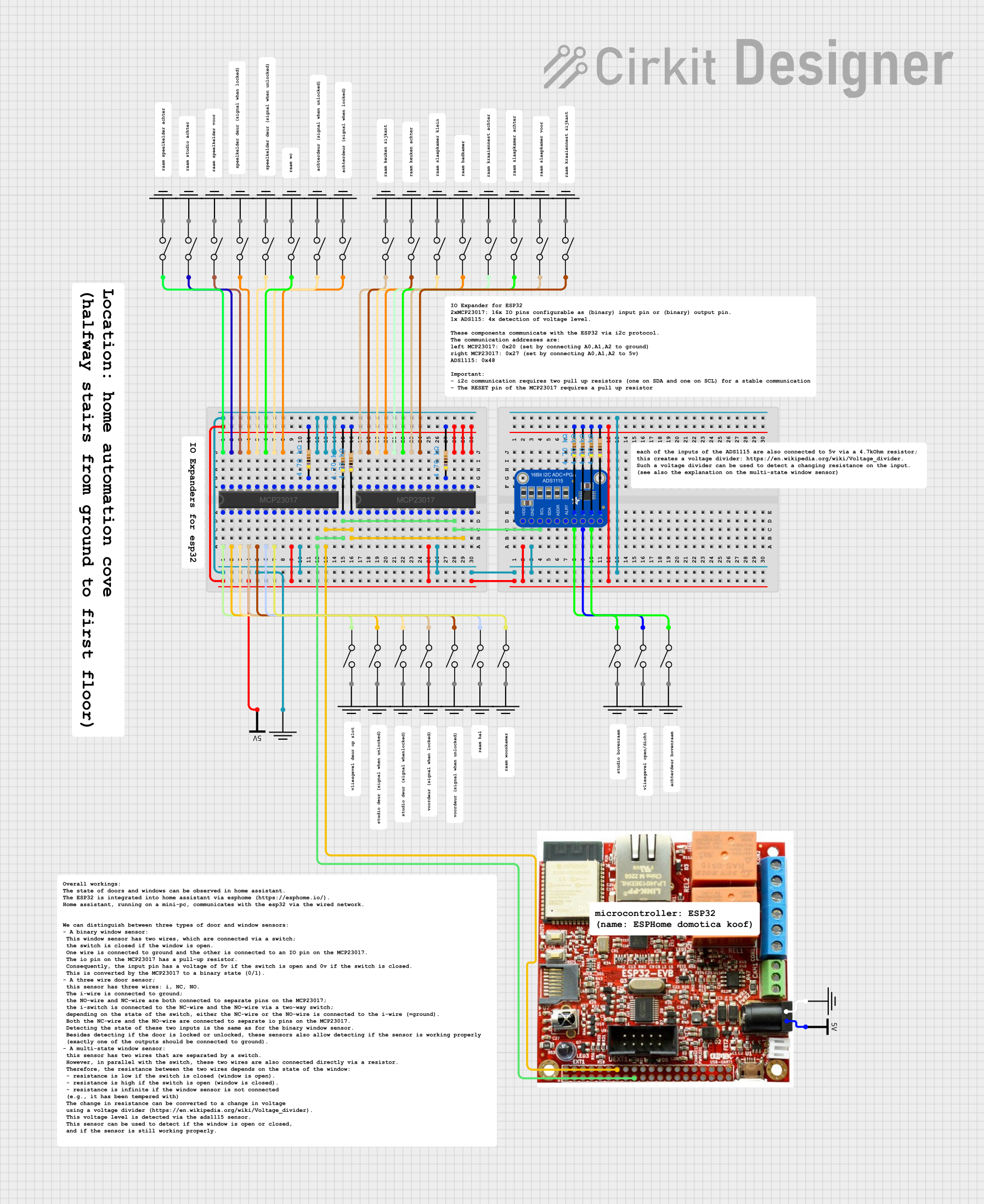
Circuit Documentation
Summary
This circuit primarily consists of two MCP23017 I/O expanders, multiple resistors, an Adafruit ADS1115 16-bit I2C ADC, a series of switches, and an Olimex ESP32-EVB microcontroller. The MCP23017 expanders are interfaced with the ESP32-EVB via I2C communication, allowing for expanded GPIO capabilities. The resistors are used for pull-ups on the I2C lines and for interfacing switches with the MCP23017 and the ADS1115 ADC. The ADS1115 ADC is used to read analog signals, which are presumably generated by the state changes of the switches. The ESP32-EVB serves as the main controller of the circuit, likely processing the input from the switches and communicating with the MCP23017 expanders.
Component List
MCP23017 I/O Expander
- 16-bit I/O expander with I2C interface
- Provides additional GPIOs
- Pins: GPB0-GPB7, GPA0-GPA7, A0-A2, SDA, SCL, VSS, VDD, INTA, INTB, RESET
Resistor
- 4.7k Ohm resistors
- Likely used as pull-up resistors for I2C lines and for switch debouncing
Adafruit ADS1115 16-Bit I2C ADC
- 16-bit precision analog-to-digital converter
- I2C interface
- Pins: VDD, GND, SCL, SDA, ADDR, ALERT, AIN0-AIN3
Switch
- Generic switches
- Used to provide input to the circuit
Olimex ESP32-EVB
- ESP32-based development board
- Provides Wi-Fi and Bluetooth connectivity
- Equipped with various GPIOs, including I2C lines
Vcc and GND
- Power supply and ground references for the circuit
Comment
- Placeholder for additional information or notes about the circuit
Wiring Details
MCP23017 I/O Expander
- VDD connected to 3.3V power supply through a 4.7k Ohm resistor
- VSS connected to GND
- SDA connected to I2C data line with a 4.7k Ohm pull-up resistor
- SCL connected to I2C clock line with a 4.7k Ohm pull-up resistor
- RESET connected to a 4.7k Ohm resistor (presumably pulled high)
- GPA0-GPA7 and GPB0-GPB7 connected to switches
Resistor
- 4.7k Ohm resistors used as pull-ups for I2C lines (SDA, SCL) and for other signal conditioning purposes
Adafruit ADS1115 16-Bit I2C ADC
- VDD connected to 3.3V power supply
- GND connected to ground
- SCL connected to I2C clock line
- SDA connected to I2C data line
- AIN0-AIN3 connected to switches through 4.7k Ohm resistors
Switch
- Connected to MCP23017 I/O expander GPIOs
- Connected to ADS1115 ADC inputs through 4.7k Ohm resistors
Olimex ESP32-EVB
- GND connected to ground
- 5V connected to 5V power supply
- GPIOs used for I2C communication with MCP23017 and ADS1115
Documented Code
No code has been provided for the microcontrollers in the circuit. The expected code would handle the initialization and communication with the I2C devices (MCP23017 and ADS1115), read the state of the switches, and perform any necessary processing or control actions based on the switch inputs.