
Arduino UNO-Based Smart Energy Meter with GSM Module and LCD Display
View and Edit Project In Cirkit Designer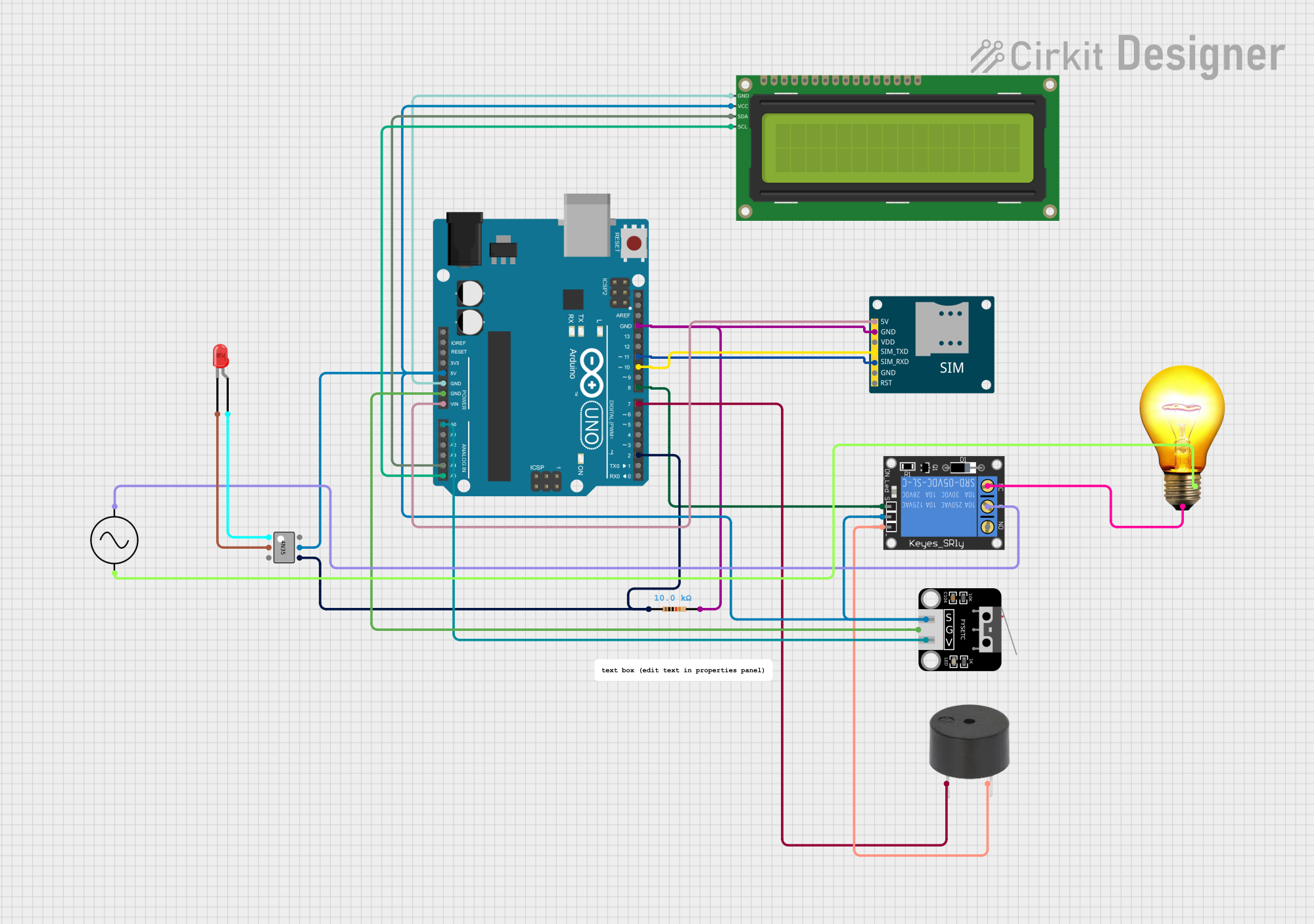
Circuit Documentation
Summary
This circuit is designed to monitor and control an energy meter using an Arduino UNO microcontroller. It includes various components such as a relay, limit switch, buzzer, GSM module, LCD display, and more. The circuit can send SMS notifications and display information on an LCD screen. It also includes a safety feature to detect theft using a limit switch.
Component List
Arduino UNO
- Description: A microcontroller board based on the ATmega328P.
- Pins: UNUSED, IOREF, Reset, 3.3V, 5V, GND, Vin, A0, A1, A2, A3, A4, A5, SCL, SDA, AREF, D13, D12, D11, D10, D9, D8, D7, D6, D5, D4, D3, D2, D1, D0
1-Channel Relay (5V 10A)
- Description: A relay module that can control high voltage devices.
- Pins: NC, signal, C, power, NO, ground
Limit Switch
- Description: A switch that can detect physical limits or positions.
- Pins: S, G, V
Buzzer
- Description: An audio signaling device.
- Pins: PIN, GND
4N35
- Description: An optocoupler for electrical isolation.
- Pins: Anode, Cathode, NC, Base, Collector, Emitter
AC Bulb
- Description: A standard AC light bulb.
- Pins: P, N
SIM800L GSM Module
- Description: A GSM module for sending and receiving SMS.
- Pins: 5V, GND, VDD, SIM_TXD, SIM_RXD, RST
Resistor
- Description: A 10k Ohm resistor.
- Pins: pin1, pin2
- Properties: Resistance: 10k Ohms
16x2 I2C LCD
- Description: A 16x2 character LCD with I2C interface.
- Pins: GND, VCC, SDA, SCL
AC Supply
- Description: An AC power supply.
- Pins: +ve, -ve
LED: Two Pin (red)
- Description: A red LED.
- Pins: cathode, anode
Wiring Details
Arduino UNO
5V connected to:
- 4N35 (Collector)
- Limit Switch (S)
- 16x2 I2C LCD (VCC)
- 1-Channel Relay (power)
GND connected to:
- 16x2 I2C LCD (GND)
- Limit Switch (G)
- Resistor (pin2)
- SIM800L GSM Module (GND)
Vin connected to:
- SIM800L GSM Module (5V)
A0 connected to:
- Limit Switch (V)
A4 connected to:
- 16x2 I2C LCD (SDA)
A5 connected to:
- 16x2 I2C LCD (SCL)
D11 connected to:
- SIM800L GSM Module (SIM_RXD)
D10 connected to:
- SIM800L GSM Module (SIM_TXD)
D8 connected to:
- 1-Channel Relay (signal)
D7 connected to:
- Buzzer (PIN)
D2 connected to:
- Resistor (pin1)
- 4N35 (Emitter)
1-Channel Relay (5V 10A)
NC connected to:
- AC Bulb (P)
C connected to:
- AC Supply (+ve)
ground connected to:
- Buzzer (GND)
4N35
Anode connected to:
- LED: Two Pin (red) (anode)
Cathode connected to:
- LED: Two Pin (red) (cathode)
AC Bulb
- N connected to:
- AC Supply (-ve)
Code Documentation
Arduino UNO Code
#include <EEPROM.h>
#include <LiquidCrystal_I2C.h>
LiquidCrystal_I2C lcd(0x27, 16, 2);

#include <SoftwareSerial.h>
SoftwareSerial GSM(10, 11);

#define buzzer 7
#define relay  8
#define bt_theft  A0

#define pulse_in 2

char inchar;

int unt_a = 0, unt_b = 0, unt_c = 0, unt_d = 0;
long total_unt = 7;

int price = 0;
long price1 = 0;

int Set = 10;

int pulse = 0;

String phone_no1 = "+919148487253";
String phone_no2 = "+919148314411";

int flag1 = 0, flag2 = 0, flag3 = 0;

void ai0() {
  // Your ISR code here
}

void initModule(const char* command, const char* response, unsigned long timeout) {
  // Your initModule code here
}

void sendSMS(String phoneNumber, String message) {
  // Your sendSMS code here
}

void Write() {
  // Your Write code here
}

void Read() {
  // Your Read code here
}

void load_on() {
  // Your load_on code here
}

void setup() {
  Serial.begin(9600);
  GSM.begin(9600);

  pinMode(bt_theft, INPUT_PULLUP);
  pinMode(relay, OUTPUT);
  pinMode(buzzer, OUTPUT);

  pinMode(pulse_in, INPUT);
  attachInterrupt(0, ai0, RISING);

  lcd.begin(16, 2); // Assuming a 16x2 LCD
  lcd.backlight();
  lcd.clear();
  lcd.setCursor(5, 0);
  lcd.print("WELCOME");
  lcd.setCursor(2, 1);
  lcd.print("Energy Meter");
  digitalWrite(buzzer, HIGH);

  Serial.println("Initializing....");
  initModule("AT", "OK", 1000);
  initModule("ATE1", "OK", 1000);
  initModule("AT+CPIN?", "READY", 1000);
  initModule("AT+CMGF=1", "OK", 1000);
  initModule("AT+CNMI=2,2,0,0,0", "OK", 1000);
  Serial.println("Initialized Successfully");
  delay(100);
  sendSMS(phone_no1, "Welcome To Energy Meter");
  digitalWrite(buzzer, LOW);
  lcd.clear();

  if (EEPROM.read(50) == 0) {}
  else {
    Write();
  }

  EEPROM.write(50, 0);

  pulse = EEPROM.read(10);

  Read();
  if (total_unt > 0) {
    digitalWrite(relay, HIGH);
  }
}

void loop() {
  if (GSM.available() > 0) {
    inchar = GSM.read();
    if (inchar == 'A') {
      delay(10);
      inchar = GSM.read();
      if (inchar == 'T') {
        delay(10);
        inchar = GSM.read();
        if (inchar == 'r') {
          delay(10);
          inchar = GSM.read();
          if (inchar == 'e') {
            delay(10);
            inchar = GSM.read();
            if (inchar == 'c') {
              delay(10);
              inchar = GSM.read();
              if (inchar == 'h') {
                delay(10);
                inchar = GSM.read();
                if (inchar == '1') {
                  price = 100 / Set;  total_unt = total_unt + price;
                  sendSMS(phone_no1, "Your Recharge is Done: 100");
                  sendSMS(phone_no2, "Your Recharge is Done: 100");
                  load_on();
                }
                else if (inchar == '2') {
                  price = 200 / Set;  total_unt = total_unt + price;
                  sendSMS(phone_no1, "Your Recharge is Done: 200");
                  sendSMS(phone_no2, "Your Recharge is Done: 200");
                  load_on();
                }
                else if (inchar == '3') {
                  price = 300 / Set;  total_unt = total_unt + price;
                  sendSMS(phone_no1, "Your Recharge is Done: 300");
                  sendSMS(phone_no2, "Your Recharge is Done: 300");
                  load_on();
                }
                else if (inchar == '4') {
                  price = 400 / Set;  total_unt = total_unt + price;
                  sendSMS(phone_no1, "Your Recharge is Done: 400");
                  sendSMS(phone_no2, "Your Recharge is Done: 400");
                  load_on();
                }
                delay(10);
              }
            }
          }