
Arduino and ESP8266-Based Gas Leakage Detection System with Wi-Fi Alerts
View and Edit Project In Cirkit Designer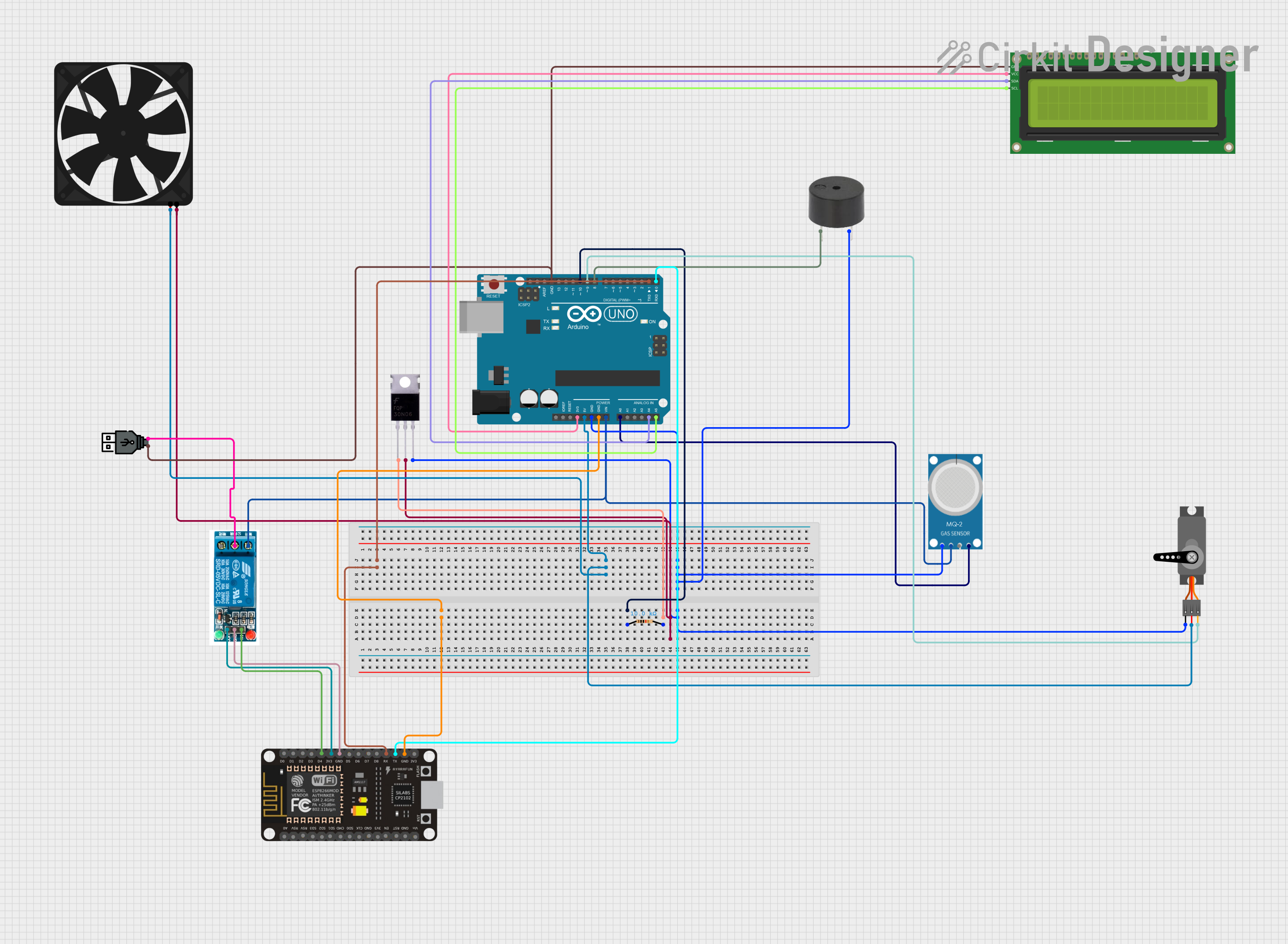
Circuit Documentation
Summary
This circuit is designed to detect gas leakage using an MQ-2 gas sensor and take appropriate actions such as activating a fan, sounding a buzzer, and moving a servo motor. The system also displays the status on a 16x2 I2C LCD and communicates with an ESP8266 NodeMCU for remote monitoring and control via Blynk.
Component List
Arduino UNO
- Description: Microcontroller board based on the ATmega328P.
- Pins: UNUSED, IOREF, Reset, 3.3V, 5V, GND, Vin, A0, A1, A2, A3, A4, A5, SCL, SDA, AREF, D13, D12, D11, D10, D9, D8, D7, D6, D5, D4, D3, D2, D1, D0
5V Relay
- Description: Electromechanical relay for switching high power devices.
- Pins: Normally Open, Common terminal, Normally Closed, In, GND, VCC
ESP8266 NodeMCU
- Description: WiFi-enabled microcontroller for IoT applications.
- Pins: D0, D1, D2, D3, D4, 3V3, GND, D5, D6, D7, D8, RX, TX, A0, RSV, SD3, SD2, SD1, CMD, SD0, CLK, EN, RST, VIN
Fan
- Description: 5V DC fan for ventilation.
- Pins: GND, 5V
16x2 I2C LCD
- Description: 16x2 character LCD with I2C interface.
- Pins: GND, VCC, SDA, SCL
Servo
- Description: Servo motor for mechanical movement.
- Pins: GND, VCC, PWM
MQ-2 Gas Sensor
- Description: Gas sensor for detecting LPG, i-butane, propane, methane, alcohol, hydrogen, and smoke.
- Pins: GND, VCC, ANALOG, Digital
Buzzer
- Description: Piezoelectric buzzer for sound alerts.
- Pins: PIN, GND
Mosfet
- Description: MOSFET transistor for switching.
- Pins: Gate, Drain, Source
Resistor
- Description: 10k Ohm resistor.
- Pins: pin1, pin2
USB Power
- Description: USB power supply.
- Pins: +, -
Wiring Details
Arduino UNO
- 3.3V to 16x2 I2C LCD VCC
- 5V to Fan 5V, Servo VCC
- GND to Servo GND, MQ-2 GND, Mosfet Source, Buzzer GND, 16x2 I2C LCD GND, ESP8266 NodeMCU GND
- Vin to MQ-2 VCC, 5V Relay Normally Open
- A0 to MQ-2 Digital
- A4 to 16x2 I2C LCD SDA
- A5 to 16x2 I2C LCD SCL
- D0 to ESP8266 NodeMCU TX
- D1 to ESP8266 NodeMCU RX
- D8 to Buzzer PIN
- D9 to Servo PWM
- D10 to Resistor pin1
5V Relay
- Normally Open to Arduino UNO Vin
- Common terminal to USB Power +
- In to ESP8266 NodeMCU D4
- GND to ESP8266 NodeMCU GND
- VCC to ESP8266 NodeMCU 3V3
ESP8266 NodeMCU
- GND to Arduino UNO GND
- RX to Arduino UNO D1
- TX to Arduino UNO D0
- D4 to 5V Relay In
- 3V3 to 5V Relay VCC
Fan
- 5V to Arduino UNO 5V
- GND to Mosfet Drain
16x2 I2C LCD
- VCC to Arduino UNO 3.3V
- GND to Arduino UNO GND
- SDA to Arduino UNO A4
- SCL to Arduino UNO A5
Servo
- VCC to Arduino UNO 5V
- GND to Arduino UNO GND
- PWM to Arduino UNO D9
MQ-2 Gas Sensor
- VCC to Arduino UNO Vin
- GND to Arduino UNO GND
- Digital to Arduino UNO A0
Buzzer
- PIN to Arduino UNO D8
- GND to Arduino UNO GND
Mosfet
- Gate to Resistor pin2
- Drain to Fan GND
- Source to Arduino UNO GND
Resistor
- pin1 to Arduino UNO D10
- pin2 to Mosfet Gate
USB Power
- + to 5V Relay Common terminal
- - to 16x2 I2C LCD GND
Code Documentation
Arduino UNO Code
#include <Wire.h>
#include <LiquidCrystal_I2C.h>
#include <Servo.h>

// Initialize the LCD with I2C address (usually 0x27)
LiquidCrystal_I2C lcd(0x27, 16, 2);

// Initialize the servo
Servo servoMotor;

// Pin Definitions
const int gasSensorPin = A0;  // MQ2 Gas Sensor (Analog)
const int fanPin = 10;        // Fan
const int buzzerPin = 8;      // Buzzer
const int servoPin = 9;       // Servo Motor
const int gasThreshold = 400; // Gas detection threshold

unsigned long lastReadingTime = 0;    // Last gas sensor reading time
const unsigned long readingInterval = 1000; // Time interval for readings (ms)

void setup() {
  lcd.init();
  lcd.backlight();
  lcd.print("System Starting...");
  delay(2000);
  lcd.clear();

  servoMotor.attach(servoPin);
  servoMotor.write(0); // Servo in safe position

  pinMode(gasSensorPin, INPUT);
  pinMode(fanPin, OUTPUT);
  pinMode(buzzerPin, OUTPUT);

  Serial.begin(9600); // For communication with NodeMCU
}

void loop() {
  unsigned long currentTime = millis();

  if (currentTime - lastReadingTime >= readingInterval) {
    lastReadingTime = currentTime;

    int gasValue = analogRead(gasSensorPin);
    String currentStatus;

    if (gasValue > gasThreshold) {
      digitalWrite(fanPin, HIGH);
      digitalWrite(buzzerPin, HIGH);
      servoMotor.write(120);
      currentStatus = "LEAKAGE DETECTED";
    } else {
      digitalWrite(fanPin, LOW);
      digitalWrite(buzzerPin, LOW);
      servoMotor.write(0);
      currentStatus = "SAFE TO USE";
    }

    // Update LCD
    lcd.setCursor(0, 0);
    lcd.print("Gas Value: ");
    lcd.print(gasValue);
    lcd.print("     ");
    lcd.setCursor(0, 1);
    lcd.print(currentStatus + "     ");

    // Send data to NodeMCU
    Serial.print(gasValue); // Gas value
    Serial.print(",");
    Serial.println(currentStatus); // Status
  }
}
ESP8266 NodeMCU Code
// Blynk credentials (Replace with actual values from Blynk IoT setup)
#define BLYNK_TEMPLATE_ID "TMPL3lOb1YZbs"
#define BLYNK_TEMPLATE_NAME "Detection"
#define BLYNK_AUTH_TOKEN "ppUqmtQehDPtfaiWC6JcgOFEWd5AWXrG"

#include <ESP8266WiFi.h>
#include <BlynkSimpleEsp8266.h>

// Blynk Auth Token, WiFi credentials
char auth[] = "ppUqmtQehDPtfaiWC6JcgOFEWd5AWXrG";
char ssid[] = "Raj";
char pass[] = "123465789";

// Pin definitions
#define RELAY_PIN D4 // Relay connected to D4

int gasStatus = 0; // Variable to store data from Arduino
String lastStatus = "UNKNOWN"; // Track last gas status to avoid duplicate notifications

BLYNK_WRITE(V0) { // Blynk button widget to control relay (Virtual Pin V0)
  int relayControl = param.asInt();
  digitalWrite(RELAY_PIN, !relayControl); // Invert logic