Cirkit Designer
Your all-in-one circuit design IDE
Home /
Project Documentation
Raspberry Pi 5 Motion-Activated Dual DC Motor System with PIR Sensors

Circuit Documentation
Summary
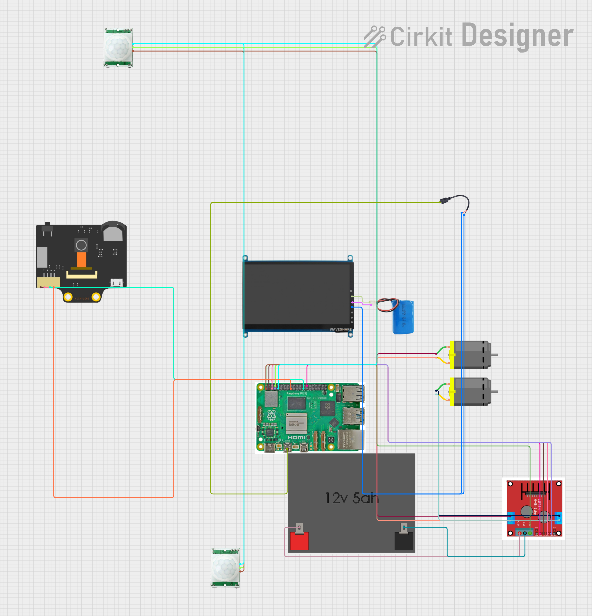
This circuit is designed to control two DC motors using a Raspberry Pi 5 microcontroller and an L298N motor driver. The motors are activated based on input from two PIR motion sensors. Additionally, a 7-inch WaveShare display is connected to the Raspberry Pi for visual output, and a Huskylens camera module is used for additional sensing capabilities.
Component List
Raspberry Pi 5
- Description: A powerful microcontroller with multiple GPIO pins, HDMI outputs, and various other interfaces.
- Pins: Type-C, Micro HDMI 1, Micro HDMI 2, Camera 1, Camera 2, PoE, Fan, PCIe, USB 3.0, USB 2.0, Ethernet, 5V, GND, 3.3v, GPIO 14, GPIO 15, GPIO 18, GPIO 23, GPIO 24, GPIO 25, GPIO 8, GPIO 7, GPIO 1, GPIO 12, GPIO 16, GPIO 20, GPIO 21, GPIO 2, GPIO 3, GPIO 4, GPIO 17, GPIO 27, GPIO 22, GPIO 10, GPIO 9, GPIO 11, GPIO 0, GPIO 5, GPIO 6, GPIO 13, GPIO 19, GPIO 26
DC Motor
- Description: A simple DC motor with two pins for power and ground.
- Pins: pin 1, pin 2
Motor Driver (L298N)
- Description: A motor driver module capable of controlling two DC motors.
- Pins: OUT 1, OUT 2, OUT 3, OUT 4, +12V INPUT, GND, +5V OUTPUT, ENA, IN 1, IN 2, IN 3, IN 4, ENB
12v5ah Battery
- Description: A 12V battery used to power the motor driver.
- Pins: 12v +, 12v -
PIR/Motion Sensor
- Description: A sensor used to detect motion.
- Pins: GND, OUTPUT, VCC
7 inch WaveShare (H)
- Description: A 7-inch display module with HDMI and USB interfaces.
- Pins: HDMI, +, -, USB Power, Touch USB, Audio, VGA
5v Battery
- Description: A 5V battery used to power the display.
- Pins: positive, negative
Micro USB to Cable (2 Pin)
- Description: A cable used to connect the Raspberry Pi to the display.
- Pins: Micro USB, +, -
Huskylense
- Description: A camera module with I2C interface.
- Pins: SDA, SCL, GND, VCC
Wiring Details
Raspberry Pi 5
- Micro HDMI 1 connected to Micro USB of Micro USB to Cable (2 Pin)
- 5V connected to +5V OUTPUT of Motor Driver (L298N)
- 3.3v connected to VCC of both PIR/Motion Sensors
- GPIO 14 connected to OUTPUT of both PIR/Motion Sensors
- GPIO 1 connected to IN 1 of Motor Driver (L298N)
- GPIO 2 connected to IN 2 of Motor Driver (L298N) and SDA of Huskylense
- GPIO 3 connected to IN 3 of Motor Driver (L298N) and SCL of Huskylense
- GPIO 4 connected to IN 4 of Motor Driver (L298N)
- GND connected to GND of both PIR/Motion Sensors and GND of Huskylense
- 3.3v connected to VCC of Huskylense
Motor Driver (L298N)
- OUT 3 connected to pin 1 of DC Motor
- OUT 4 connected to pin 2 of DC Motor
- OUT 1 connected to pin 1 of another DC Motor
- OUT 2 connected to pin 2 of another DC Motor
- +12V INPUT connected to 12v + of 12v5ah Battery
- GND connected to 12v - of 12v5ah Battery
7 inch WaveShare (H)
- + connected to positive of 5v Battery
- - connected to negative of 5v Battery
- USB Power connected to + and - of Micro USB to Cable (2 Pin)
Code Documentation
Raspberry Pi 5 Code
/*
 * This Arduino Sketch is designed for a Raspberry Pi 5 microcontroller.
 * The circuit includes two DC motors controlled via an L298N motor driver.
 * The motors are controlled based on input from two PIR motion sensors.
 * The code initializes the GPIO pins and sets up the motor control logic.
 * The motors will run when motion is detected by the sensors.
 */

// Define motor driver pins
#define IN1 1
#define IN2 2
#define IN3 3
#define IN4 4

// Define PIR sensor pin
#define PIR_SENSOR 14

void setup() {
  // Initialize motor driver pins as outputs
  pinMode(IN1, OUTPUT);
  pinMode(IN2, OUTPUT);
  pinMode(IN3, OUTPUT);
  pinMode(IN4, OUTPUT);

  // Initialize PIR sensor pin as input
  pinMode(PIR_SENSOR, INPUT);
}

void loop() {
  // Read PIR sensor value
  int pirValue = digitalRead(PIR_SENSOR);

  // If motion is detected, run the motors
  if (pirValue == HIGH) {
    // Motor 1 forward
    digitalWrite(IN1, HIGH);
    digitalWrite(IN2, LOW);
    // Motor 2 forward
    digitalWrite(IN3, HIGH);
    digitalWrite(IN4, LOW);
  } else {
    // Stop motors
    digitalWrite(IN1, LOW);
    digitalWrite(IN2, LOW);
    digitalWrite(IN3, LOW);
    digitalWrite(IN4, LOW);
  }

  // Small delay to debounce PIR sensor
  delay(100);
}
DC Motor Code
void setup() {
  // put your setup code here, to run once:
}

void loop() {
  // put your main code here, to run repeatedly:
}
This documentation provides a comprehensive overview of the circuit, including a summary, detailed component list, wiring details, and the code used in the microcontroller.