Cirkit Designer
Your all-in-one circuit design IDE
Home /
Project Documentation
Arduino UNO-Based Secure Entry System with RFID, Keypad, and LCD Display
Secure Entry Management System Documentation
Summary
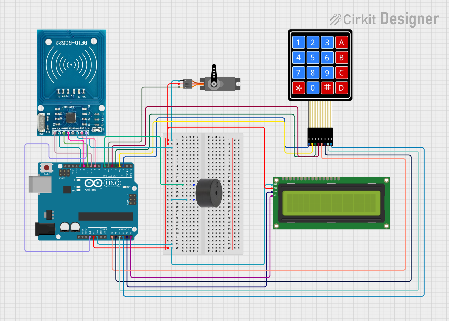
This document provides a detailed overview of a Secure Entry Management System designed using an Arduino UNO microcontroller. The system integrates an RFID-RC522 module, a 4x4 membrane matrix keypad, an I2C LCD 16x2 screen, a servo motor, and a buzzer. The system provides real-time feedback and controls a locking mechanism based on user input and RFID authentication.
Component List
Arduino UNO
- Description: Microcontroller board based on the ATmega328P.
- Pins: UNUSED, IOREF, Reset, 3.3V, 5V, GND, Vin, A0, A1, A2, A3, A4, A5, SCL, SDA, AREF, D13, D12, D11, D10, D9, D8, D7, D6, D5, D4, D3, D2, D1, D0
I2C LCD 16x2 Screen
- Description: 16x2 character LCD display with I2C interface.
- Pins: SCL, SDA, VCC (5V), GND, VDD, VO, RS, RW, E, D0, D1, D2, D3, D4, D5, D6, D7, BLA, BLK
RFID-RC522
- Description: RFID module for reading and writing RFID tags.
- Pins: VCC (3.3V), RST, GND, IRQ, MISO, MOSI, SCK, SDA
4X4 Membrane Matrix Keypad
- Description: 4x4 matrix keypad for user input.
- Pins: R1, R2, R3, R4, C1, C2, C3, C4
Servo
- Description: Servo motor for controlling the locking mechanism.
- Pins: GND, VCC, PWM
Buzzer
- Description: Buzzer for audio feedback.
- Pins: PIN, GND
Wiring Details
Arduino UNO
- 5V to I2C LCD 16x2 Screen VCC (5V)
- 5V to Servo VCC
- 3.3V to RFID-RC522 VCC (3.3V)
- GND to I2C LCD 16x2 Screen GND
- GND to Servo GND
- GND to RFID-RC522 GND
- GND to Buzzer GND
- A0 to 4X4 Membrane Matrix Keypad C1
- A1 to 4X4 Membrane Matrix Keypad C2
- A2 to 4X4 Membrane Matrix Keypad C3
- A3 to 4X4 Membrane Matrix Keypad C4
- A4 to I2C LCD 16x2 Screen SDA
- A5 to I2C LCD 16x2 Screen SCL
- D2 to 4X4 Membrane Matrix Keypad R1
- D3 to 4X4 Membrane Matrix Keypad R2
- D4 to 4X4 Membrane Matrix Keypad R3
- D5 to 4X4 Membrane Matrix Keypad R4
- D6 to Servo PWM
- D7 to Buzzer PIN
- D9 to RFID-RC522 RST
- D10 to RFID-RC522 SDA
- D11 to RFID-RC522 MOSI
- D12 to RFID-RC522 MISO
- D13 to RFID-RC522 SCK
I2C LCD 16x2 Screen
- VCC (5V) to Arduino UNO 5V
- GND to Arduino UNO GND
- SDA to Arduino UNO A4
- SCL to Arduino UNO A5
RFID-RC522
- VCC (3.3V) to Arduino UNO 3.3V
- GND to Arduino UNO GND
- RST to Arduino UNO D9
- SDA to Arduino UNO D10
- MOSI to Arduino UNO D11
- MISO to Arduino UNO D12
- SCK to Arduino UNO D13
4X4 Membrane Matrix Keypad
- C1 to Arduino UNO A0
- C2 to Arduino UNO A1
- C3 to Arduino UNO A2
- C4 to Arduino UNO A3
- R1 to Arduino UNO D2
- R2 to Arduino UNO D3
- R3 to Arduino UNO D4
- R4 to Arduino UNO D5
Servo
- VCC to Arduino UNO 5V
- GND to Arduino UNO GND
- PWM to Arduino UNO D6
Buzzer
- PIN to Arduino UNO D7
- GND to Arduino UNO GND
Code Documentation
/*
 * Secure Entry Management System
 * This Arduino sketch controls an access system using an RFID-RC522 module,
 * a 4x4 membrane matrix keypad, an I2C LCD 16x2 screen, a servo motor, and
 * a buzzer. The system provides real-time feedback and controls a locking
 * mechanism based on user input and RFID authentication.
 */

#include <Wire.h>
#include <LiquidCrystal_I2C.h>
#include <Servo.h>
#include <MFRC522.h>
#include <Keypad.h>

// Pin definitions
#define RST_PIN 9
#define SS_PIN 10
#define BUZZER_PIN 7
#define SERVO_PIN 6

// Create instances
LiquidCrystal_I2C lcd(0x27, 16, 2);
Servo myServo;
MFRC522 rfid(SS_PIN, RST_PIN);

// Keypad setup
const byte ROWS = 4;
const byte COLS = 4;
char keys[ROWS][COLS] = {
  {'1','2','3','A'},
  {'4','5','6','B'},
  {'7','8','9','C'},
  {'*','0','#','D'}
};
byte rowPins[ROWS] = {2, 3, 4, 5};
byte colPins[COLS] = {A0, A1, A2, A3};
Keypad keypad = Keypad(makeKeymap(keys), rowPins, colPins, ROWS, COLS);

void setup() {
  // Initialize serial communication
  Serial.begin(9600);
  // Initialize LCD
  lcd.begin();
  lcd.backlight();
  // Initialize Servo
  myServo.attach(SERVO_PIN);
  myServo.write(0); // Lock position
  // Initialize RFID
  SPI.begin();
  rfid.PCD_Init();
  // Initialize Buzzer
  pinMode(BUZZER_PIN, OUTPUT);
  // Welcome message
  lcd.setCursor(0, 0);
  lcd.print("Welcome!");
  lcd.setCursor(0, 1);
  lcd.print("Scan your card");
}

void loop() {
  // Check for RFID card
  if (rfid.PICC_IsNewCardPresent() && rfid.PICC_ReadCardSerial()) {
    lcd.clear();
    lcd.setCursor(0, 0);
    lcd.print("Card detected");
    // Add your RFID authentication logic here
    // For now, we assume the card is valid
    lcd.setCursor(0, 1);
    lcd.print("Access Granted");
    myServo.write(90); // Unlock position
    digitalWrite(BUZZER_PIN, HIGH);
    delay(1000);
    digitalWrite(BUZZER_PIN, LOW);
    delay(5000); // Keep unlocked for 5 seconds
    myServo.write(0); // Lock position
    lcd.clear();
    lcd.setCursor(0, 0);
    lcd.print("Welcome!");
    lcd.setCursor(0, 1);
    lcd.print("Scan your card");
  }
  // Check for keypad input
  char key = keypad.getKey();
  if (key) {
    lcd.clear();
    lcd.setCursor(0, 0);
    lcd.print("Key pressed:");
    lcd.setCursor(0, 1);
    lcd.print(key);
    // Add your keypad handling logic here
    delay(1000);
    lcd.clear();
    lcd.setCursor(0, 0);
    lcd.print("Welcome!");
    lcd.setCursor(0, 1);
    lcd.print("Scan your card");
  }
}
This code initializes the components and provides the main logic for the Secure Entry Management System. The system checks for RFID card presence and keypad input, providing appropriate feedback and controlling the servo motor and buzzer accordingly.