
ESP32-Controlled Ultrasonic Distance Measurement with LCD Display
View and Edit Project In Cirkit Designer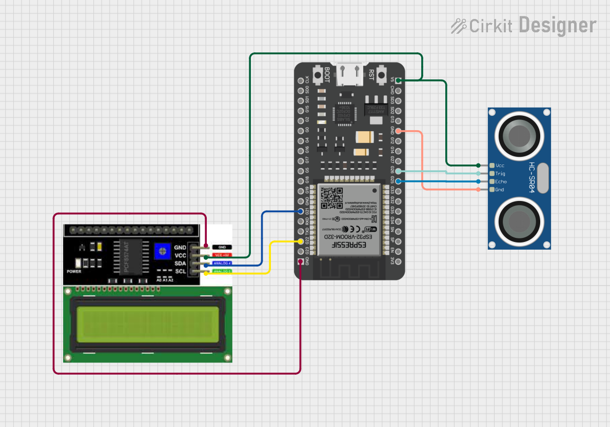
Circuit Documentation
Summary of the Circuit
This circuit integrates an ESP32 microcontroller with an HC-SR04 Ultrasonic Sensor and an LCD I2C Display. The ESP32 serves as the central processing unit, controlling the ultrasonic sensor to measure distances and displaying the results on the LCD screen. The ultrasonic sensor is powered and triggered by the ESP32, which also reads the sensor's echo signal to calculate the distance to an object. The LCD display, connected via I2C, shows the distance measurements.
Component List
HC-SR04 Ultrasonic Sensor
- Pins: VCC, TRIG, ECHO, GND
- Description: This sensor measures distances by emitting ultrasonic waves and timing the echo received back.
- Purpose: To provide distance measurements to the ESP32 for processing and display.
LCD I2C Display
- Pins: GND, VCC, SDA, SCL
- Description: A display module with an I2C interface for showing information.
- Purpose: To display distance measurements received from the ESP32.
ESP32 - 38 pins
- Pins: 3V3, EN, SP, SN, G34, G35, G32, G33, G25, G26, G27, G14, G12, GND, G13, SD2, SD3, CMD, 5V, G23, G22, TXD, RXD, G21, G19, G18, G5, G17, G16, G4, G0, G2, G15, SD1, SD0, CLK
- Description: A microcontroller with Wi-Fi and Bluetooth capabilities and a wide range of GPIO pins.
- Purpose: To control the ultrasonic sensor and the LCD display, process sensor data, and manage communication and data display.
Wiring Details
HC-SR04 Ultrasonic Sensor
- VCC: Connected to the 5V output from the ESP32.
- TRIG: Connected to GPIO 26 on the ESP32.
- ECHO: Connected to GPIO 25 on the ESP32.
- GND: Connected to the ground (GND) on the ESP32.
LCD I2C Display
- GND: Connected to the ground (GND) on the ESP32.
- VCC: Connected to the 5V output from the ESP32.
- SDA: Connected to GPIO 21 (SDA) on the ESP32.
- SCL: Connected to GPIO 22 (SCL) on the ESP32.
ESP32 - 38 pins
- 5V: Provides power to the HC-SR04 Ultrasonic Sensor and the LCD I2C Display.
- G26: Sends trigger signal to the HC-SR04 Ultrasonic Sensor.
- G25: Receives echo signal from the HC-SR04 Ultrasonic Sensor.
- GND: Common ground for the circuit.
- G21 (SDA): I2C data line for the LCD I2C Display.
- G22 (SCL): I2C clock line for the LCD I2C Display.
Documented Code
No code has been provided for the microcontroller. The documentation for the code section will be updated once the code is available. The expected code should initialize the ESP32's GPIO pins for communication with the HC-SR04 Ultrasonic Sensor and the LCD I2C Display, handle the timing and calculation for distance measurement, and manage the display of the measured distance on the LCD screen.