
Circuit Documentation
Summary of the Circuit
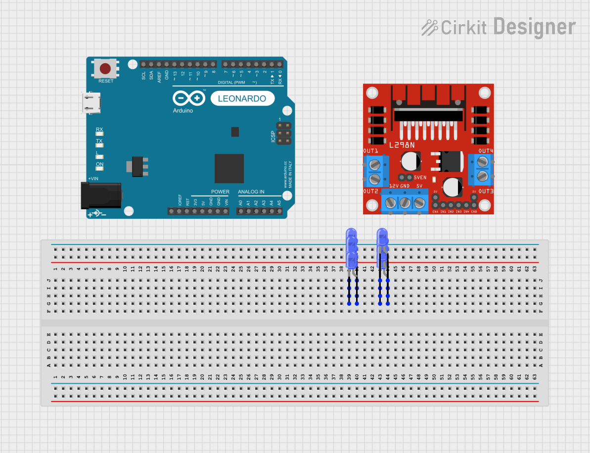
The circuit in question appears to be a simple LED array setup controlled by an Arduino Leonardo (Rev3b) and interfaced with an L298N DC motor driver. The LEDs are arranged in two separate groups, each group sharing common cathodes and anodes respectively. There is no embedded code provided for the microcontroller, which suggests that the circuit might be in an early stage of development or that the code is to be developed separately.
Component List
L298N DC Motor Driver
- Description: A motor driver module capable of driving two DC motors.
- Pins: OUT1, OUT2, 12V, GND, 5V, OUT3, OUT4, 5V-ENA-JMP-I, 5V-ENA-JMP-O, +5V-J1, +5V-J2, ENA, IN1, IN2, IN3, IN4, ENB
Arduino Leonardo (Rev3b)
- Description: A microcontroller board based on the ATmega32u4.
- Pins: D0/RX, D1/TX, D2/SDA, D3 PWM/SCL, D4/A6, D5 PWM, D6 PWM/A7, D7, n.c., IOREF, RESET, 3V3, 5V, GND, VIN, A0, A1, A2, A3, A4, A5, D8/A8, D9 PWM/A9, D10 PWM/A10, D11 PWM, D12/A11, D13 PWM, AREF, SDA, SCL
LEDs: Two Pin (blue)
- Description: Standard blue LEDs with two pins, an anode, and a cathode.
Wiring Details
L298N DC Motor Driver
- OUT1: Not connected
- OUT2: Not connected
- 12V: Not connected
- GND: Not connected
- 5V: Not connected
- OUT3: Not connected
- OUT4: Not connected
- 5V-ENA-JMP-I: Not connected
- 5V-ENA-JMP-O: Not connected
- +5V-J1: Not connected
- +5V-J2: Not connected
- ENA: Not connected
- IN1: Not connected
- IN2: Not connected
- IN3: Not connected
- IN4: Not connected
- ENB: Not connected
Arduino Leonardo (Rev3b)
- D0/RX: Not connected
- D1/TX: Not connected
- D2/SDA: Not connected
- D3 PWM/SCL: Not connected
- D4/A6: Not connected
- D5 PWM: Not connected
- D6 PWM/A7: Not connected
- D7: Not connected
- n.c.: Not connected
- IOREF: Not connected
- RESET: Not connected
- 3V3: Not connected
- 5V: Not connected
- GND: Not connected
- VIN: Not connected
- A0: Not connected
- A1: Not connected
- A2: Not connected
- A3: Not connected
- A4: Not connected
- A5: Not connected
- D8/A8: Not connected
- D9 PWM/A9: Not connected
- D10 PWM/A10: Not connected
- D11 PWM: Not connected
- D12/A11: Not connected
- D13 PWM: Not connected
- AREF: Not connected
- SDA: Not connected
- SCL: Not connected
LEDs: Two Pin (blue)
- Group 1:
- Cathodes: Connected together
- Anodes: Connected together
- Group 2:
- Cathodes: Connected together
- Anodes: Connected together
Documented Code
No code has been provided for the microcontroller. The documentation of the code will be added once the code is available. The expected code will likely initialize the pins connected to the LEDs as outputs and then control them to turn the LEDs on or off.
Please note that the wiring details are based on the provided electrical net list, which does not show any connections to the power supply or the microcontroller. This suggests that the circuit is incomplete or that the provided information is partial. Further details would be required to complete the documentation.