
Arduino UNO Controlled RGB LED Matrix with Bluetooth Connectivity and Audio Output
View and Edit Project In Cirkit Designer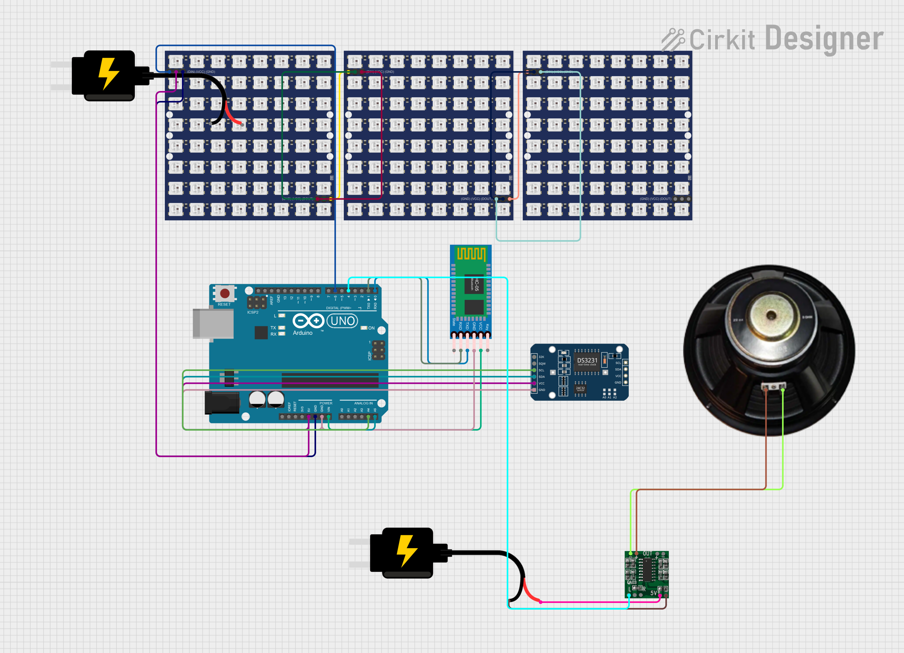
Circuit Documentation
Summary of the Circuit
This circuit is designed to interface various components with an Arduino UNO microcontroller. The components include WS2812 RGB LED matrices, a speaker driven by a PAM8403 amplifier, an HC-05 Bluetooth module for wireless communication, and a DS3231 Real-Time Clock (RTC) for timekeeping. The circuit is powered by two separate DC 5V sources, one for the PAM8403 amplifier and the other for the rest of the components. The Arduino UNO controls the LED matrices and communicates with the Bluetooth module and RTC.
Component List
Arduino UNO
- Microcontroller board based on the ATmega328P
- It has 14 digital input/output pins, 6 analog inputs, a 16 MHz quartz crystal, a USB connection, a power jack, an ICSP header, and a reset button.
Speaker
- An electroacoustic transducer used to produce sound
WS2812 RGB LED matrix 8x8 (x3)
- An 8x8 matrix of individually addressable RGB LEDs
- Each LED can be controlled with a single data line using a high-speed one-wire protocol.
HC-05 Bluetooth Module
- A wireless communication module that allows for serial communication via Bluetooth
DS3231 RTC
- A highly accurate I2C real-time clock with an integrated temperature-compensated crystal oscillator (TCXO) and crystal.
DC Source 5V (x2)
- Provides a regulated 5V power supply to the circuit components
PAM8403
- A small digital amplifier chip that provides high-quality sound amplification
Wiring Details
Arduino UNO
- 5V pin connected to the VCC pins of the WS2812 RGB LED matrices and the DS3231 RTC
- GND pin connected to the GND pins of the WS2812 RGB LED matrices, the HC-05 Bluetooth Module, and the DS3231 RTC
- Vin pin connected to the VCC pin of the HC-05 Bluetooth Module
- A4 pin connected to the SCL pin of the DS3231 RTC
- A5 pin connected to the SDA pin of the DS3231 RTC
- D6 pin connected to the DIN pin of the first WS2812 RGB LED matrix
- D4 pin connected to the L-INPUT pin of the PAM8403
- D1 pin connected to the RXD pin of the HC-05 Bluetooth Module
- D0 pin connected to the TXD pin of the HC-05 Bluetooth Module
Speaker
- "+" pin connected to the L+ pin of the PAM8403
- "-" pin connected to the L- pin of the PAM8403
WS2812 RGB LED matrix 8x8
- VCC pins connected to the 5V pin of the Arduino UNO
- GND pins connected to the GND pin of the Arduino UNO
- DIN pin of the first matrix connected to the D6 pin of the Arduino UNO
- DOUT pin of the first matrix connected to the DIN pin of the second matrix
- DOUT pin of the second matrix connected to the DIN pin of the third matrix
HC-05 Bluetooth Module
- VCC pin connected to the Vin pin of the Arduino UNO
- GND pin connected to the GND pin of the Arduino UNO
- TXD pin connected to the D0 pin of the Arduino UNO
- RXD pin connected to the D1 pin of the Arduino UNO
DS3231 RTC
- VCC pin connected to the 5V pin of the Arduino UNO
- GND pin connected to the GND pin of the Arduino UNO
- SCL pin connected to the A4 pin of the Arduino UNO
- SDA pin connected to the A5 pin of the Arduino UNO
DC Source 5V
- VCC pin of one source connected to the 5vIN+ pin of the PAM8403
- GND pin of the same source connected to the GND/IN- pin of the PAM8403
PAM8403
- 5vIN+ pin connected to the VCC pin of one DC Source 5V
- GND/IN- pin connected to the GND pin of the same DC Source 5V
- L-INPUT pin connected to the D4 pin of the Arduino UNO
- L+ pin connected to the "+" pin of the Speaker
- L- pin connected to the "-" pin of the Speaker
Documented Code
Arduino UNO Code (sketch.ino)
void setup() {
  // put your setup code here, to run once:

}

void loop() {
  // put your main code here, to run repeatedly:

}
Note: The provided code for the Arduino UNO is a template with empty setup and loop functions. The actual functionality needs to be implemented based on the specific requirements of the circuit.