ESP32-Controlled Ultrasonic Water Level Monitor with PH Sensing and Relay-Operated Pump
Circuit Documentation
Summary
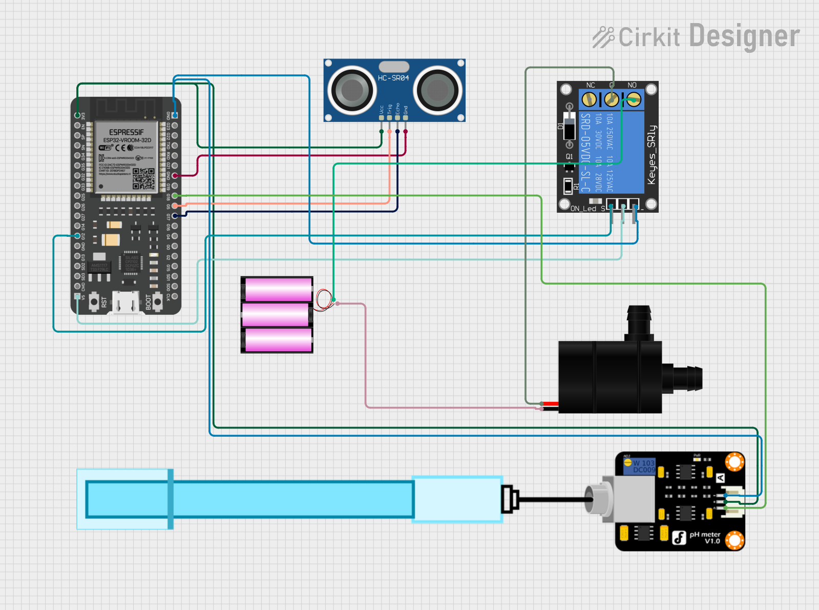
The circuit in question is designed to interface an ESP32 microcontroller with a set of sensors and actuators for monitoring and control purposes. The circuit includes an HC-SR04 Ultrasonic Sensor for distance measurement, a PH Meter for chemical analysis of liquids, a 1-Channel Relay to control a Water Pump, and a 12V battery to power the Water Pump. The ESP32 serves as the central processing unit, reading sensor data and controlling the relay based on programmed logic.
Component List
HC-SR04 Ultrasonic Sensor
- Description: A sensor used to measure distance via ultrasonic waves.
- Pins: VCC, TRIG, ECHO, GND
Water Pump
- Description: An actuator used to pump water.
- Pins: VCC, GND
1-Channel Relay (5V 10A)
- Description: An electromechanical switch used to control high power devices.
- Pins: NC (Normally Closed), signal, C (Common), power, NO (Normally Open), ground
ESP32 - 38 pins
- Description: A microcontroller with Wi-Fi and Bluetooth capabilities.
- Pins: 3V3, EN, SP, SN, G34, G35, G32, G33, G25, G26, G27, G14, G12, GND, G13, SD2, SD3, CMD, 5V, G23, G22, TXD, RXD, G21, G19, G18, G5, G17, G16, G4, G0, G2, G15, SD1, SD0, CLK
Battery 12v
- Description: A power source for the circuit.
- Pins: +, -
PH Meter
- Description: A sensor used to measure the acidity or alkalinity of a liquid.
- Pins: Signal, VCC, GND
Wiring Details
HC-SR04 Ultrasonic Sensor
- VCC connected to ESP32 3V3
- TRIG connected to ESP32 G5
- ECHO connected to ESP32 G17
- GND connected to ESP32 GND
Water Pump
- VCC connected to 1-Channel Relay C
- GND connected to Battery 12V -
1-Channel Relay (5V 10A)
- NC not connected
- signal connected to ESP32 G12
- C connected to Water Pump VCC
- power connected to ESP32 5V
- NO connected to Battery 12V +
- ground connected to ESP32 GND
ESP32 - 38 pins
- 3V3 connected to HC-SR04 VCC and PH Meter VCC
- G5 connected to HC-SR04 TRIG
- G17 connected to HC-SR04 ECHO
- GND connected to HC-SR04 GND, 1-Channel Relay ground, and PH Meter GND
- G12 connected to 1-Channel Relay signal
- 5V connected to 1-Channel Relay power
- G18 connected to PH Meter Signal
Battery 12v
- connected to 1-Channel Relay NO
- connected to Water Pump GND
PH Meter
- Signal connected to ESP32 G18
- VCC connected to ESP32 3V3
- GND connected to ESP32 GND
Documented Code
No code was provided for the microcontroller. The documentation of the code would typically include a description of the functionality, setup, and loop routines, as well as any functions or libraries used to interface with the sensors and actuators. Since no code is available, this section cannot be completed.