
Circuit Documentation
Summary
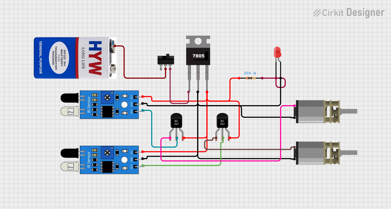
This document provides a detailed overview of a circuit that includes various components such as IR sensors, a voltage regulator, a 9V battery, DC motors, LEDs, resistors, a toggle switch, and transistors. The circuit is designed to utilize IR sensors to control the operation of DC motors and an LED, with power regulation provided by a 7805 voltage regulator and a 9V battery.
Component List
IR Sensor
- Pins: out, gnd, vcc
- Description: Infrared sensor used for detecting objects.
7805 Voltage Regulator
- Pins: Vin, Gnd, Vout
- Description: Voltage regulator to provide a stable 5V output.
9V Battery
- Pins: +, -
- Description: Power source for the circuit.
DC Mini Metal Gear Motor
- Pins: IN1, IN2
- Description: DC motor used for mechanical movement.
LED: Two Pin (red)
- Pins: cathode, anode
- Description: Red LED for visual indication.
Resistor
- Pins: pin1, pin2
- Description: Resistor with a resistance of 200 Ohms.
Toggle Switch
- Pins: L1, COM, L2
- Description: Switch to control the power supply.
BC547 Transistor
- Pins: Collector, Base, Emitter
- Description: NPN transistor used for switching.
Wiring Details
IR Sensor 1
- out: Connected to the Base of BC547 Transistor 2.
- gnd: Connected to the Gnd of 7805, IN2 of both DC Mini Metal Gear Motors, and the anode of the LED.
- vcc: Connected to the Vout of 7805, pin1 of the Resistor, and the Emitter of both BC547 Transistors.
IR Sensor 2
- out: Connected to the Base of BC547 Transistor 1.
- gnd: Connected to the Gnd of 7805, IN2 of both DC Mini Metal Gear Motors, and the anode of the LED.
- vcc: Connected to the Vout of 7805, pin1 of the Resistor, and the Emitter of both BC547 Transistors.
7805 Voltage Regulator
- Vin: Connected to L2 of the Toggle Switch.
- Gnd: Connected to the gnd of both IR Sensors, IN2 of both DC Mini Metal Gear Motors, and the anode of the LED.
- Vout: Connected to the vcc of both IR Sensors, pin1 of the Resistor, and the Emitter of both BC547 Transistors.
9V Battery
- +: Connected to COM of the Toggle Switch.
- -: Not connected in the provided net list.
DC Mini Metal Gear Motor 1
- IN1: Connected to the Collector of BC547 Transistor 1.
- IN2: Connected to the gnd of both IR Sensors, Gnd of 7805, and the anode of the LED.
DC Mini Metal Gear Motor 2
- IN1: Connected to the Collector of BC547 Transistor 2.
- IN2: Connected to the gnd of both IR Sensors, Gnd of 7805, and the anode of the LED.
LED: Two Pin (red)
- cathode: Connected to pin2 of the Resistor.
- anode: Connected to the gnd of both IR Sensors, Gnd of 7805, and IN2 of both DC Mini Metal Gear Motors.
Resistor
- pin1: Connected to the Vout of 7805, vcc of both IR Sensors, and the Emitter of both BC547 Transistors.
- pin2: Connected to the cathode of the LED.
Toggle Switch
- L2: Connected to Vin of 7805.
- COM: Connected to the + of the 9V Battery.
- L1: Not connected in the provided net list.
BC547 Transistor 1
- Collector: Connected to IN1 of DC Mini Metal Gear Motor 1.
- Base: Connected to the out of IR Sensor 2.
- Emitter: Connected to the Vout of 7805, vcc of both IR Sensors, and pin1 of the Resistor.
BC547 Transistor 2
- Collector: Connected to IN1 of DC Mini Metal Gear Motor 2.
- Base: Connected to the out of IR Sensor 1.
- Emitter: Connected to the Vout of 7805, vcc of both IR Sensors, and pin1 of the Resistor.
Code
No microcontroller code is provided for this circuit.
This document provides a comprehensive overview of the circuit, including a summary, detailed component list, wiring details, and code documentation.