
LilyPad Arduino and Accelerometer-Based Wearable Fitness Tracker with Heart Rate Monitoring
View and Edit Project In Cirkit Designer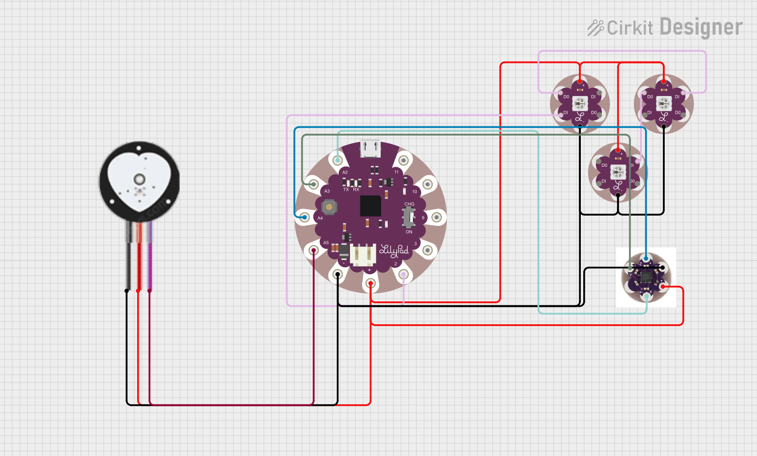
Circuit Documentation
Summary
The circuit in question is designed to integrate a LilyPad Arduino USB with multiple LilyPad Pixel Boards, a Heart Pulse Sensor, and a LilyPad Accelerometer. The LilyPad Arduino USB serves as the central microcontroller unit, interfacing with the sensors and controlling the Pixel Boards. The accelerometer provides three-axis motion data, while the Heart Pulse Sensor monitors the pulse rate. The Pixel Boards are likely used for visual feedback or display. The circuit is powered through the 3.3V output from the LilyPad Arduino USB, with a common ground shared across all components.
Component List
LilyPad Arduino USB
- Description: A microcontroller board based on the ATmega32u4, designed for wearables and e-textiles. It can be powered via USB or an external power supply.
- Pins: 3V3, GND, A2, A3, A4, A5, D2, D3, D9, D10, D11
LilyPad Pixel Board
- Description: An addressable RGB LED module designed for use with the LilyPad system. It can be daisy-chained to create various lighting effects.
- Pins: DI (Data In), DO (Data Out), VCC, GND
Heart Pulse Sensor
- Description: A sensor that measures the heart rate by detecting the pulse through the fingertip or earlobe.
- Pins: SIGNAL, VCC, GND
LilyPad Accelerometer
- Description: A sensor that measures acceleration in three axes: X, Y, and Z.
- Pins: X, Y, Z, VCC, GND
Wiring Details
LilyPad Arduino USB
- 3V3: Connected to VCC of LilyPad Pixel Boards, LilyPad Accelerometer, and Heart Pulse Sensor.
- GND: Connected to GND of LilyPad Pixel Boards, LilyPad Accelerometer, and Heart Pulse Sensor.
- A2: Connected to X pin of LilyPad Accelerometer.
- A3: Connected to Y pin of LilyPad Accelerometer.
- A4: Connected to Z pin of LilyPad Accelerometer.
- A5: Connected to SIGNAL pin of Heart Pulse Sensor.
- D2: Connected to DI (Data In) of the first LilyPad Pixel Board in the daisy chain.
LilyPad Pixel Board (First in Daisy Chain)
- DI (Data In): Connected to D2 of LilyPad Arduino USB.
- DO (Data Out): Connected to DI (Data In) of the next LilyPad Pixel Board in the daisy chain.
- VCC: Connected to 3V3 of LilyPad Arduino USB.
- GND: Connected to GND of LilyPad Arduino USB.
LilyPad Pixel Board (Subsequent in Daisy Chain)
- DI (Data In): Connected to DO (Data Out) of the previous LilyPad Pixel Board in the daisy chain.
- DO (Data Out): Connected to DI (Data In) of the next LilyPad Pixel Board in the daisy chain (if any).
- VCC: Connected to 3V3 of LilyPad Arduino USB.
- GND: Connected to GND of LilyPad Arduino USB.
Heart Pulse Sensor
- SIGNAL: Connected to A5 of LilyPad Arduino USB.
- VCC: Connected to 3V3 of LilyPad Arduino USB.
- GND: Connected to GND of LilyPad Arduino USB.
LilyPad Accelerometer
- X: Connected to A2 of LilyPad Arduino USB.
- Y: Connected to A3 of LilyPad Arduino USB.
- Z: Connected to A4 of LilyPad Arduino USB.
- VCC: Connected to 3V3 of LilyPad Arduino USB.
- GND: Connected to GND of LilyPad Arduino USB.
Documented Code
No code has been provided for the microcontrollers in the circuit. To fully utilize the hardware, embedded code should be written and uploaded to the LilyPad Arduino USB. The code should initialize and read data from the accelerometer and heart pulse sensor, control the Pixel Boards based on sensor inputs or predefined patterns, and handle any necessary communication or data processing tasks.