
Circuit Documentation
Summary
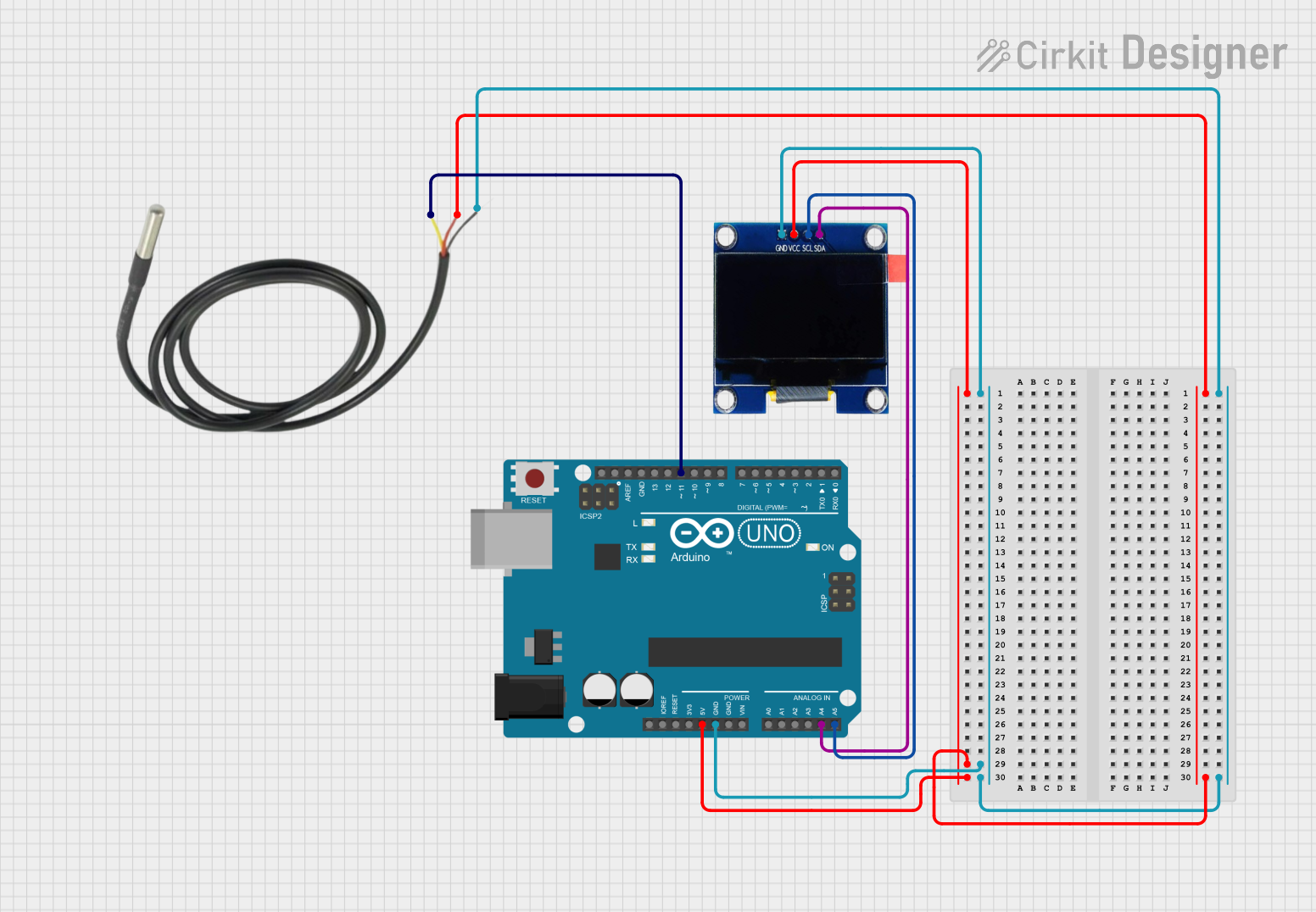
This circuit consists of an Arduino UNO microcontroller, an OLED 1.3" display, and a temperature sensor. The Arduino UNO serves as the central processing unit, controlling the OLED display to visualize data and reading temperature values from the temperature sensor. The OLED display is used to show graphical data or information, while the temperature sensor provides real-time temperature readings. The circuit is designed to operate with a 5V power supply, which is distributed to the components from the Arduino's 5V output pin. Communication between the Arduino and the OLED display is established via the I2C protocol, using the SCL and SDA lines. The temperature sensor is interfaced with the Arduino through a digital input pin.
Component List
Arduino UNO
- Description: A microcontroller board based on the ATmega328P.
- Purpose: Acts as the central processing unit for the circuit, interfacing with the OLED display and the temperature sensor.
OLED 1.3" Display
- Description: A small display with 128x64 pixel resolution.
- Purpose: Used to display graphical data or information controlled by the Arduino UNO.
Temperature Sensor
- Description: A sensor that measures temperature.
- Purpose: Provides real-time temperature readings to the Arduino UNO.
Wiring Details
Arduino UNO
- 5V: Powers the OLED display and the temperature sensor.
- GND: Common ground for the circuit.
- A4 (SDA): I2C data line connected to the OLED display.
- A5 (SCL): I2C clock line connected to the OLED display.
- D11: Digital input connected to the temperature sensor's data line.
OLED 1.3" Display
- GND: Connected to the Arduino's ground.
- VCC: Powered by the Arduino's 5V output.
- SCL: Connected to the Arduino's A5 pin for I2C clock.
- SDA: Connected to the Arduino's A4 pin for I2C data.
Temperature Sensor
- Temp GND Black: Connected to the Arduino's ground.
- Temp VDD Red: Powered by the Arduino's 5V output.
- Temp DQ Data Yellow: Connected to the Arduino's D11 pin for data communication.
Documented Code
#include "U8glib.h"

U8GLIB_SSD1306_128X64 u8g(U8G_I2C_OPT_DEV_0 | U8G_I2C_OPT_NO_ACK | U8G_I2C_OPT_FAST);

// Bitmap array representing the graphical data to be displayed on the OLED
const unsigned char epd_bitmap_oiltempupdated [] PROGMEM = {
  // Bitmap data omitted for brevity
};

int progress = 0;   // Progress of the gauge

void setup() {
  pinMode(A0, INPUT);
  u8g.setFont(u8g_font_tpssb);  // Set the font for the display
  u8g.setColorIndex(1);         // Set the color to white
}

void loop() {
  u8g.firstPage();
  do {
    u8g.setColorIndex(1);  // Set the color to white
    u8g.drawBitmapP(0, 0, 128/8, 64, epd_bitmap_oiltempupdated);
    u8g.setColorIndex(0);  // Set the color to black
    u8g.drawBox(2, 25, 125, 11);
    u8g.setColorIndex(1);  // Set the color to white
    u8g.drawBox(2, 25, map(progress, 0, 1023, 0, 125), 11);
  } while ( u8g.nextPage() );

  progress = analogRead(A0);  // Read the analog value from pin A0
}
Code Explanation
- The code includes the
U8gliblibrary, which is used for controlling the OLED display. - A bitmap array
epd_bitmap_oiltempupdatedis defined to store the graphical data to be displayed. - The
setup()function initializes the display settings and sets the A0 pin as an input. - The
loop()function continuously updates the display with the bitmap and a progress bar that represents the analog reading from pin A0. - The
map()function is used to scale the analog reading to the width of the progress bar on the display.