ESP32-Controlled 4-Channel Relay for AC Power Management
Circuit Documentation
Summary
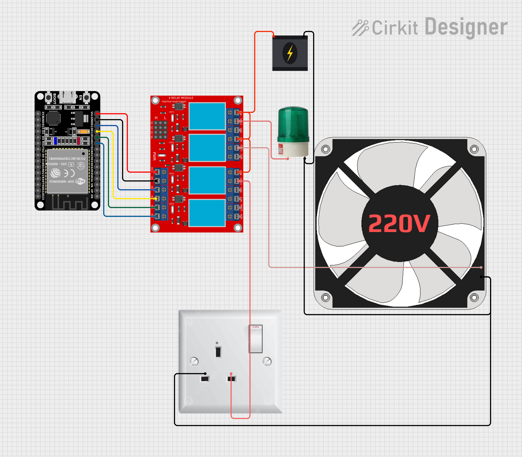
The circuit in question appears to be designed to control a 220V AC fan and a green light using an ESP32 microcontroller and a 4-channel relay module. The ESP32 is responsible for sending control signals to the relay module, which in turn switches the fan and the light on or off. The 240V power source provides the necessary power to the fan and the light, while the AC wall plug point is used to connect the power source to the relay module. The ESP32 is powered separately.
Component List
ESP32 (30 pin)
- Description: A microcontroller with WiFi and Bluetooth capabilities, featuring a wide range of GPIO pins.
- Purpose: Acts as the control unit for the circuit, sending signals to the relay module to switch the fan and light.
4 channel relay module
- Description: A module with four relays capable of controlling high power devices.
- Purpose: Receives signals from the ESP32 to switch the 220V fan and green light on or off.
240v Power Source
- Description: Provides a 240V AC power supply.
- Purpose: Powers the 220V fan and green light through the relay module.
220 fan
- Description: A standard 220V AC fan.
- Purpose: Provides air circulation, controlled by the relay module.
Green light 220vac
- Description: A 220V AC green indicator light.
- Purpose: Acts as an indicator, controlled by the relay module.
AC wall plug point
- Description: A wall-mounted AC power outlet.
- Purpose: Connects the 240V power source to the relay module.
Wiring Details
ESP32 (30 pin)
- D27: Connected to IN 4 on the 4 channel relay module.
- D14: Connected to IN 3 on the 4 channel relay module.
- D12: Connected to IN 2 on the 4 channel relay module.
- D13: Connected to IN 1 on the 4 channel relay module.
- GND: Connected to VCC- (GND) on the 4 channel relay module.
- Vin: Connected to VCC+ on the 4 channel relay module.
4 channel relay module
- IN 1 - IN 4: Controlled by the ESP32 (30 pin) to switch the relays.
- COM 3: Connected to L on the AC wall plug point.
- N.C. 1, N.C. 2, N.C. 3: Connected to Live on the 240v Power Source.
- COM 2: Connected to L on the 220 fan.
- COM 1: Connected to + on the green light 220vac.
- VCC+: Powered by Vin from the ESP32 (30 pin).
- VCC- (GND): Ground connection from GND on the ESP32 (30 pin).
240v Power Source
- Live: Connected to N.C. 1, N.C. 2, N.C. 3 on the 4 channel relay module.
- Neutral: Connected to N on the 220 fan, - on the green light 220vac, and N on the AC wall plug point.
220 fan
- L: Connected to COM 2 on the 4 channel relay module.
- N: Connected to Neutral on the 240v Power Source.
Green light 220vac
- +: Connected to COM 1 on the 4 channel relay module.
- -: Connected to Neutral on the 240v Power Source.
AC wall plug point
- L: Connected to COM 3 on the 4 channel relay module.
- N: Connected to Neutral on the 240v Power Source.
Documented Code
No code has been provided for the ESP32 microcontroller. The expected code should initialize the GPIO pins connected to the relay module and set them as outputs. It should also include logic to control the state of each relay based on some criteria, such as a schedule, sensor input, or network commands.
Without the actual code, we cannot provide a detailed documentation of the software part of this circuit. Once the code is available, it should be documented here with explanations of the functions, logic, and any libraries used.