Cirkit Designer
Your all-in-one circuit design IDE
Home /
Project Documentation
Arduino UNO Controlled Servo System with Environmental Sensing
Circuit Documentation
Summary
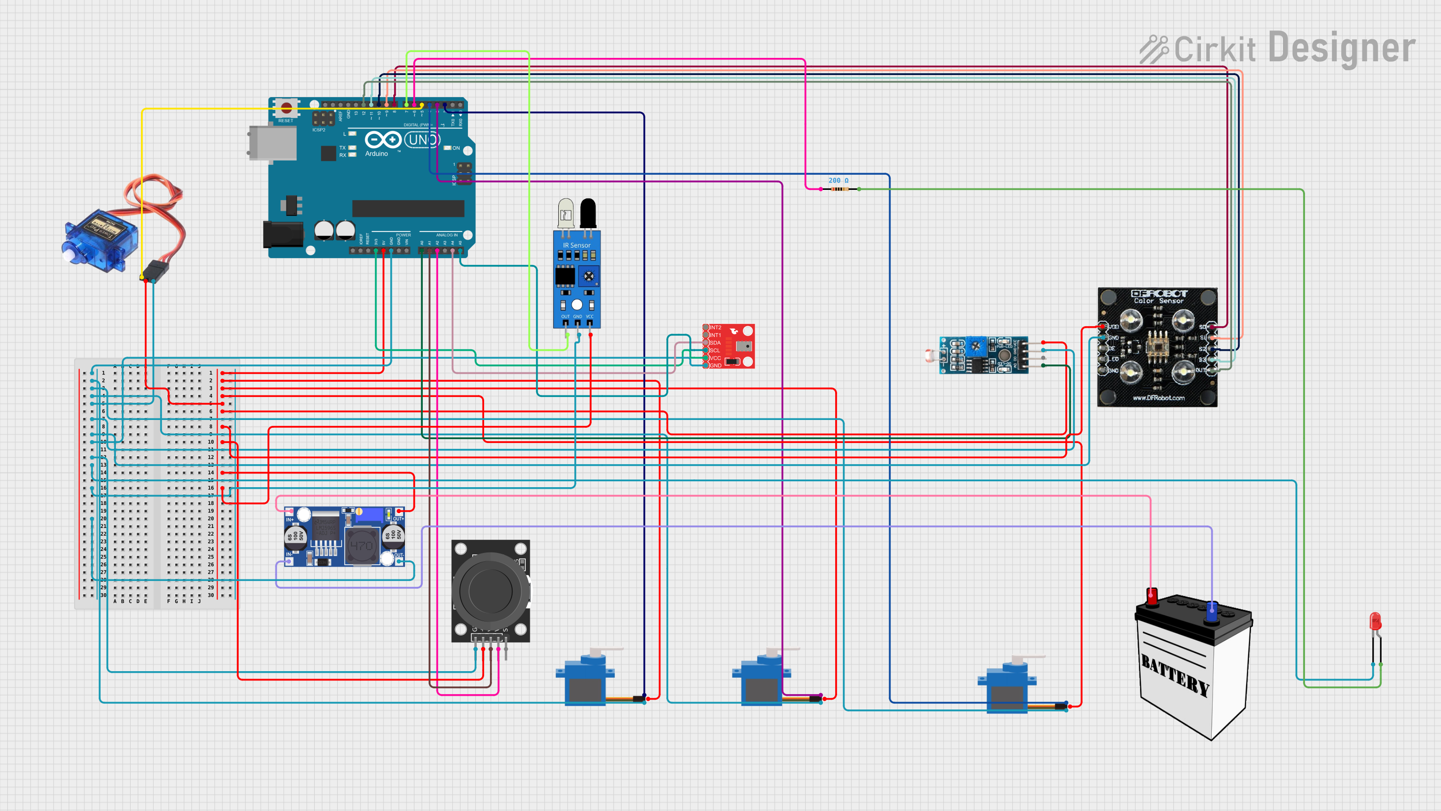
This circuit is designed around an Arduino UNO microcontroller, which serves as the central processing unit. The circuit includes various components such as servo motors, sensors, a joystick module, an LED with a resistor, a buck converter, and a 12V battery. The Arduino UNO controls and interfaces with these components, receiving sensor inputs and driving actuators like servos and LEDs. The circuit is powered by a 12V battery, which is stepped down to a lower voltage using a buck converter to power the 5V and 3.3V components.
Component List
Arduino UNO
- Microcontroller board based on the ATmega328P
- It has 14 digital input/output pins, 6 analog inputs, a 16 MHz quartz crystal, a USB connection, a power jack, an ICSP header, and a reset button.
Servo Motors
- Three generic servo components with control pulse, positive supply, and ground connections.
- One specific servo motor with signal, power, and ground connections.
LED: Two Pin (red)
- A basic red LED with an anode and cathode.
KY-023 Dual Axis Joystick Module
- A joystick module with ground, +5V, two variable resistors for X and Y axes, and a switch.
Resistor
- A single resistor with a resistance of 200 Ohms.
Buck Converter
- A device that converts a higher input voltage to a lower output voltage.
- It has input positive (IN+), input negative (IN-), output positive (OUT+), and output negative (OUT-).
12V Battery
- A power source with a voltage supply (VCC) and ground (GND).
Module LDR
- A light-dependent resistor module with a digital output (DO), analog output (AO), voltage supply (VCC), and ground (GND).
Altitude/Pressure Sensor - MPL3115A2 Breakout
- A sensor for measuring altitude and pressure with SDA, SCL, two interrupt outputs (INT1, INT2), voltage supply (VCC), and ground (GND).
RGB Colour Sensor
- A sensor for detecting color with S0-S3 control pins, output (OUT), voltage supply (Vcc), ground (GND), output enable (OE), and LED control.
IR Sensor
- An infrared sensor with an output (out), ground (gnd), and voltage supply (vcc).
Wiring Details
Arduino UNO
- Ground (GND) connected to the ground of all components.
- 5V output connected to the positive supply of servo motors, sensors, and the joystick module.
- 3.3V output connected to the VCC of the Altitude/Pressure Sensor.
- Analog pins A0, A1, and A2 connected to the analog outputs of the Module LDR and the joystick module.
- I2C pins A4 (SDA) and A5 (SCL) connected to the Altitude/Pressure Sensor.
- Digital pins D2 to D12 connected to various components for control and data acquisition.
Servo Motors
- All servos connected to a common ground and 5V supply from the Arduino UNO.
- Control pulses provided by digital pins D2, D3, and D4 of the Arduino UNO.
LED: Two Pin (red)
- Cathode connected to the ground.
- Anode connected to one end of the resistor, whose other end is connected to digital pin D6 of the Arduino UNO.
KY-023 Dual Axis Joystick Module
- Ground and +5V connected to the Arduino UNO.
- VRx and VRy connected to analog pins A1 and A2 of the Arduino UNO.
Resistor
- Connected in series with the LED and digital pin D6 of the Arduino UNO.
Buck Converter
- Input connected to the 12V battery.
- Output provides a regulated voltage to the Arduino UNO and other 5V components.
12V Battery
- Provides power to the buck converter.
Module LDR
- VCC and GND connected to the Arduino UNO.
- AO connected to analog pin A0 of the Arduino UNO.
Altitude/Pressure Sensor - MPL3115A2 Breakout
- VCC connected to the 3.3V output of the Arduino UNO.
- GND connected to the ground.
- SDA and SCL connected to the I2C pins A4 and A5 of the Arduino UNO.
RGB Colour Sensor
- Vcc and GND connected to the Arduino UNO.
- S0 to S3 control pins connected to digital pins D8 to D11 of the Arduino UNO.
- OUT connected to digital pin D12 of the Arduino UNO.
IR Sensor
- Vcc and gnd connected to the Arduino UNO.
- Out connected to digital pin D7 of the Arduino UNO.
Documented Code
Arduino UNO Code (sketch.ino)
void setup() {
  // put your setup code here, to run once:

}

void loop() {
  // put your main code here, to run repeatedly:

}
Note: The provided code is a template and does not contain any functional code. It needs to be populated with setup and loop functions to control the components as per the circuit design.