
Battery-Powered Robotic Vehicle with STM32 and L298N Motor Driver
View and Edit Project In Cirkit Designer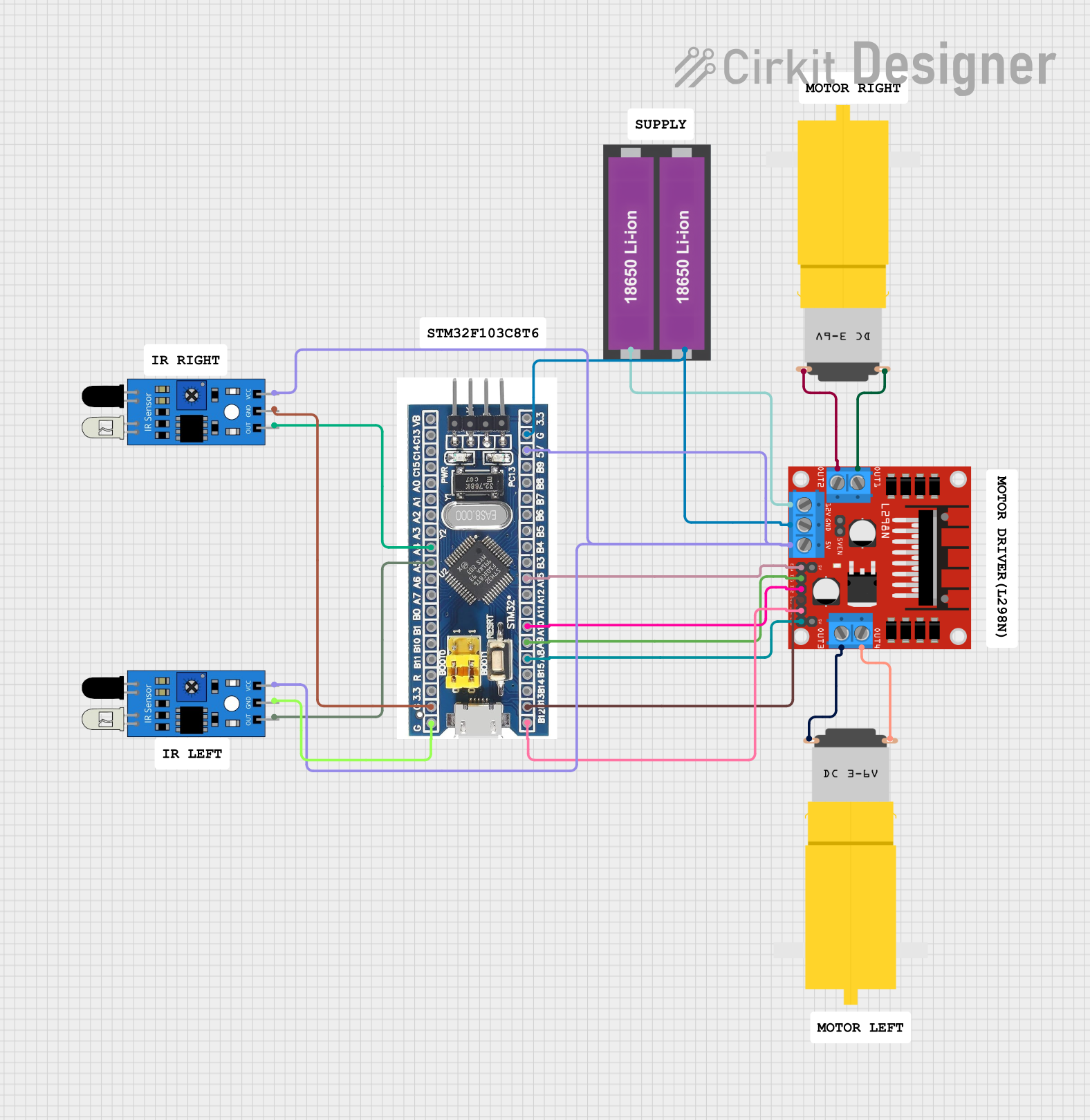
Circuit Documentation
Summary
This document provides a detailed overview of a circuit designed to control two DC motors using an L298N motor driver and an STM32F103C8T6 microcontroller. The circuit also includes two IR sensors for obstacle detection and is powered by two 18650 Li-ion batteries.
Component List
L298N DC Motor Driver
- Description: A dual H-Bridge motor driver that allows control of the speed and direction of two DC motors.
- Pins: OUT1, OUT2, 12V, GND, 5V, OUT3, OUT4, 5V-ENA-JMP-I, 5V-ENA-JMP-O, +5V-J1, +5V-J2, ENA, IN1, IN2, IN3, IN4, ENB
IR Sensor
- Description: An infrared sensor used for obstacle detection.
- Pins: out, gnd, vcc
Motor (Yellow Gear Motor)
- Description: A hobby motor with a gearbox for increased torque.
- Pins: vcc, GND
18650 Li-ion Battery x 2
- Description: A pair of rechargeable lithium-ion batteries.
- Pins: +, -
STM32F103C8T6
- Description: A 32-bit ARM Cortex-M3 microcontroller.
- Pins: GND, 3.3V, reset, B11, B10, B1, B0, A7, A6, A5, A4, A3, A2, A1, A0, C15, C14, C13, VBT, 3.3, 5V, B12, B13, b14, B15, A8, A9, A10, A11, A12, A15, B3, B4, B5, B6, B7, B8, B9, SWIO, SWCLK
Wiring Details
L298N DC Motor Driver
- GND connected to GND of STM32F103C8T6 and - of 18650 Li-ion Battery
- 5V connected to vcc of both IR sensors and 5V of STM32F103C8T6
- IN4 connected to B12 of STM32F103C8T6
- IN3 connected to B13 of STM32F103C8T6
- ENB connected to A8 of STM32F103C8T6
- IN1 connected to A9 of STM32F103C8T6
- IN2 connected to A10 of STM32F103C8T6
- ENA connected to A15 of STM32F103C8T6
- OUT1 connected to GND of one Yellow Gear Motor
- OUT2 connected to vcc of one Yellow Gear Motor
- OUT3 connected to GND of the other Yellow Gear Motor
- OUT4 connected to vcc of the other Yellow Gear Motor
- 12V connected to + of 18650 Li-ion Battery
IR Sensor 1
- gnd connected to GND of STM32F103C8T6
- vcc connected to 5V of L298N DC Motor Driver
- out connected to A5 of STM32F103C8T6
IR Sensor 2
- gnd connected to GND of STM32F103C8T6
- vcc connected to 5V of L298N DC Motor Driver
- out connected to A4 of STM32F103C8T6
Motor (Yellow Gear Motor) 1
- GND connected to OUT1 of L298N DC Motor Driver
- vcc connected to OUT2 of L298N DC Motor Driver
Motor (Yellow Gear Motor) 2
- GND connected to OUT3 of L298N DC Motor Driver
- vcc connected to OUT4 of L298N DC Motor Driver
18650 Li-ion Battery x 2
- + connected to 12V of L298N DC Motor Driver
- - connected to GND of L298N DC Motor Driver and GND of STM32F103C8T6
STM32F103C8T6
- GND connected to GND of L298N DC Motor Driver, gnd of both IR sensors, and - of 18650 Li-ion Battery
- 5V connected to 5V of L298N DC Motor Driver and vcc of both IR sensors
- A5 connected to out of IR Sensor 1
- A4 connected to out of IR Sensor 2
- B12 connected to IN4 of L298N DC Motor Driver
- B13 connected to IN3 of L298N DC Motor Driver
- A8 connected to ENB of L298N DC Motor Driver
- A9 connected to IN1 of L298N DC Motor Driver
- A10 connected to IN2 of L298N DC Motor Driver
- A15 connected to ENA of L298N DC Motor Driver
Code
No code is provided for this circuit.