Cirkit Designer
Your all-in-one circuit design IDE
Home /
Project Documentation
Arduino UNO Controlled Relay with DS3231 RTC

Circuit Documentation
Summary
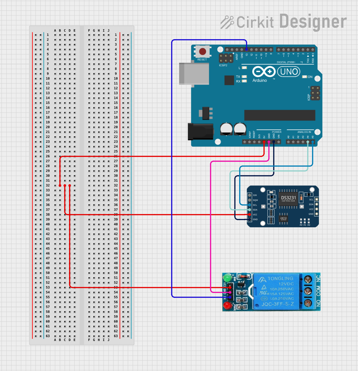
This circuit integrates an Arduino UNO microcontroller with a 12V single-channel relay and a DS3231 Real-Time Clock (RTC) module. The Arduino UNO serves as the central processing unit, controlling the relay and interfacing with the RTC module. The relay allows for controlling high-power devices, and the RTC provides accurate timekeeping. The circuit is designed to operate with a common ground and a shared 5V power supply from the Arduino UNO.
Component List
Arduino UNO
- Description: A microcontroller board based on the ATmega328P.
- Pins: UNUSED, IOREF, Reset, 3.3V, 5V, GND, Vin, A0-A5, SCL, SDA, AREF, D0-D13
- Purpose: Acts as the central controller for the circuit, providing I/O capabilities and power distribution.
12V Single Channel Relay
- Description: An electromechanical switch that allows for controlling high-power devices using a low-power signal.
- Pins: NC (Normally Closed), COM (Common), NO (Normally Open), IN (Input), GND (Ground), VCC (Voltage Supply)
- Purpose: Enables the Arduino to control high-power devices safely.
DS3231 RTC
- Description: A highly accurate I2C real-time clock with an integrated temperature-compensated crystal oscillator (TCXO) and crystal.
- Pins: 32K, SQW, SCL, SDA, VCC, GND
- Purpose: Provides precise timekeeping and can be used to schedule events or log timestamps.
Wiring Details
Arduino UNO
- 5V connected to the VCC of the 12V Single Channel Relay and DS3231 RTC.
- GND connected to the GND of the 12V Single Channel Relay and DS3231 RTC.
- A4 (SDA) connected to the SDA pin of the DS3231 RTC.
- A5 (SCL) connected to the SCL pin of the DS3231 RTC.
- D13 connected to the IN pin of the 12V Single Channel Relay.
12V Single Channel Relay
- VCC connected to the 5V pin of the Arduino UNO.
- GND connected to the GND pin of the Arduino UNO.
- IN connected to the D13 pin of the Arduino UNO.
DS3231 RTC
- VCC connected to the 5V pin of the Arduino UNO.
- GND connected to the GND pin of the Arduino UNO.
- SDA connected to the A4 pin of the Arduino UNO.
- SCL connected to the A5 pin of the Arduino UNO.
Documented Code
Arduino UNO Code (sketch.ino)
// The code for the Arduino UNO is currently empty.
Additional Documentation (documentation.txt)
// There is no additional documentation provided in the code files.
Please note that the actual functionality of the circuit will depend on the implementation of the code for the Arduino UNO, which is not provided in the inputs. The code should be written to initialize and use the RTC for timekeeping and to control the relay based on the desired logic.