Arduino Nano-Controlled LED Display with RTC and Humidity Sensing
Circuit Documentation
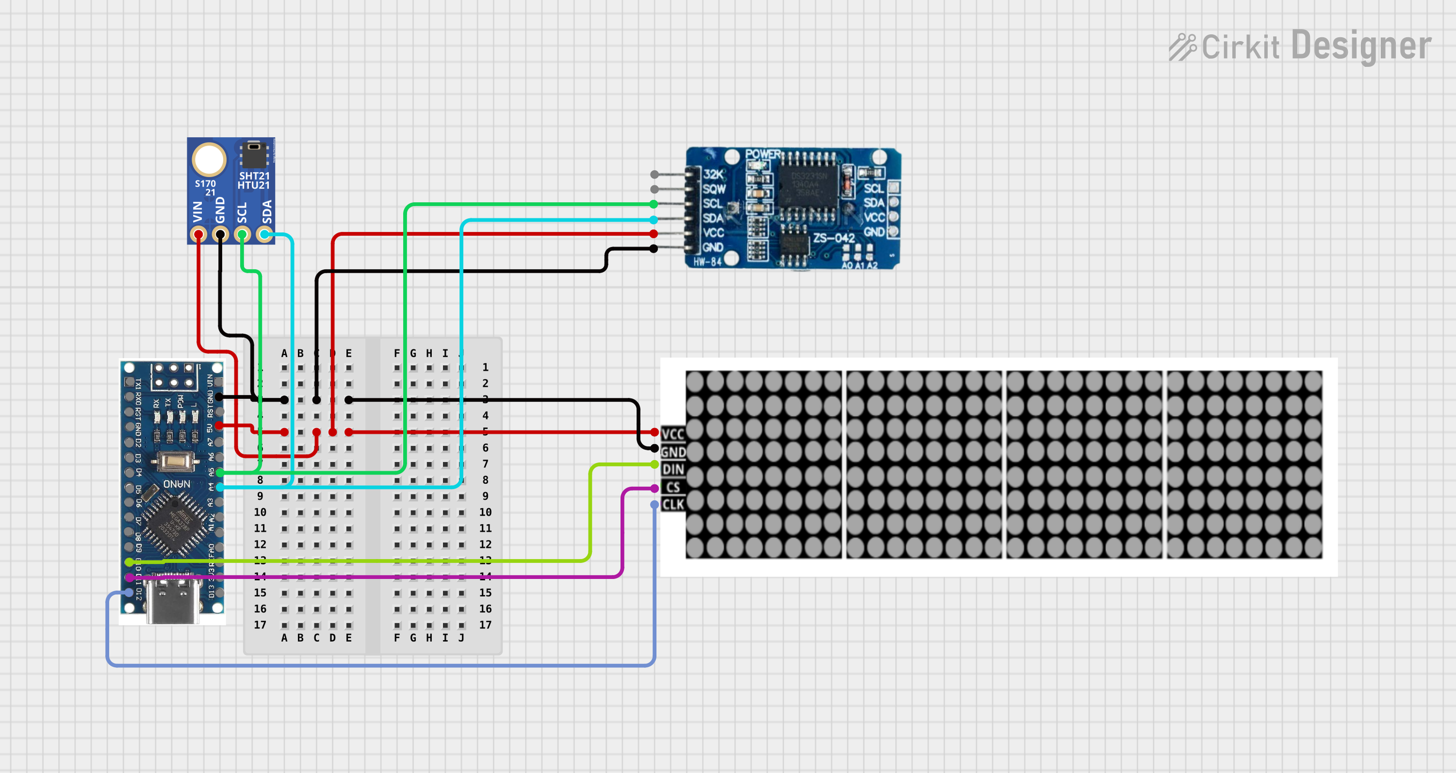
Summary
The circuit in question is designed to interface a microcontroller with a real-time clock (RTC), a humidity and temperature sensor (SHT21), and an LED dot display. The microcontroller serves as the central processing unit, controlling the LED display and communicating with the RTC and sensor via I2C communication protocol. The LED dot display is used for visual output, while the RTC provides timekeeping functionality, and the SHT21 sensor measures environmental temperature and humidity.
Component List
LED DOT DISPLAY
- Pins: VCC, GND, DIN, CS, CLK
- Description: This component is an LED dot matrix display used for visual output. It requires a power supply (VCC and GND) and communicates with the microcontroller through DIN (Data Input), CS (Chip Select), and CLK (Clock).
RTC DS3231
- Pins: 32K, SQW, SCL, SDA, VCC, GND
- Description: The DS3231 is a real-time clock module that provides accurate timekeeping with a built-in temperature-compensated crystal oscillator (TCXO) and crystal. It communicates with the microcontroller via the I2C protocol (SCL and SDA) and is powered by VCC and GND.
Nano 3.0 ATmega328P Type-C USB CH340 Controller Board
- Pins: D13, 3V3, REF, A0, A1, A2, A3, A4, A5, A6, A7, 5V, RST, GND, VIN, D11, D10, D9, D8, D7, D6, D5, D4, D3, D2, RX0, TX1, D12
- Description: This is a microcontroller board based on the ATmega328P. It has digital and analog I/O pins and supports serial communication. It can be powered through VIN or 5V pin and has a ground pin (GND).
SHT21
- Pins: VIN, GND, SCL, SDA
- Description: The SHT21 is a digital humidity and temperature sensor that provides calibrated, linearized signals in digital form. It uses I2C communication (SCL and SDA) and is powered by VIN and GND.
Wiring Details
LED DOT DISPLAY
- VCC: Connected to the 5V power supply.
- GND: Connected to the ground.
- DIN: Connected to the D10 pin of the Nano 3.0 ATmega328P microcontroller.
- CS: Connected to the D11 pin of the Nano 3.0 ATmega328P microcontroller.
- CLK: Connected to the D12 pin of the Nano 3.0 ATmega328P microcontroller.
RTC DS3231
- GND: Connected to the ground.
- VCC: Connected to the 5V power supply.
- SCL: Connected to the A5 pin of the Nano 3.0 ATmega328P microcontroller.
- SDA: Connected to the A4 pin of the Nano 3.0 ATmega328P microcontroller.
Nano 3.0 ATmega328P Type-C USB CH340 Controller Board
- 5V: Provides power to the LED DOT DISPLAY and RTC DS3231.
- GND: Common ground for all components.
- A4 (SDA): Connected to the SDA pin of the RTC DS3231 and SHT21 sensor.
- A5 (SCL): Connected to the SCL pin of the RTC DS3231 and SHT21 sensor.
- D10: Connected to the DIN pin of the LED DOT DISPLAY.
- D11: Connected to the CS pin of the LED DOT DISPLAY.
- D12: Connected to the CLK pin of the LED DOT DISPLAY.
SHT21
- VIN: Connected to the 5V power supply.
- GND: Connected to the ground.
- SCL: Connected to the A5 pin of the Nano 3.0 ATmega328P microcontroller.
- SDA: Connected to the A4 pin of the Nano 3.0 ATmega328P microcontroller.
Documented Code
No code has been provided for the microcontroller. The expected functionality would include initializing the I2C communication, reading data from the RTC DS3231 and SHT21 sensor, and controlling the LED DOT DISPLAY to show the information. Without the code, we cannot document the specific implementation details. However, the code would typically include libraries for I2C communication, RTC control, sensor data acquisition, and LED display manipulation.