
Arduino UNO Rain Sensor Controlled Automatic Cover with Solar-Powered Battery Backup
View and Edit Project In Cirkit Designer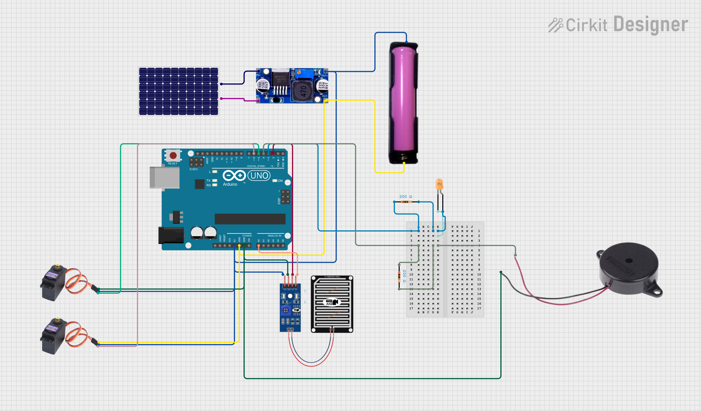
Circuit Documentation
Summary
This circuit is designed to monitor a rain sensor and control two servos to manage a cover. When rain is detected, one servo pulls the cover to close it, and when no rain is detected, the other servo rolls the cover back. The system is powered by a solar panel and a battery, with the solar panel charging the battery when there is sunlight. The circuit also includes an LED and a buzzer to provide visual and auditory alerts when rain is detected.
Component List
RAIN SENSOR
- Pins: AO, DO, GRD, VCC
- Description: Detects rain and provides both analog and digital outputs.
Arduino UNO
- Pins: UNUSED, IOREF, Reset, 3.3V, 5V, GND, Vin, A0, A1, A2, A3, A4, A5, SCL, SDA, AREF, D13, D12, D11, D10, D9, D8, D7, D6, D5, D4, D3, D2, D1, D0
- Description: Microcontroller used to control the servos, read the rain sensor, and manage the LED and buzzer.
Solar Panel
- Pins: +, -
- Description: Provides power to the system by charging the battery.
LM2596
- Pins: IN, OUT
- Description: Voltage regulator used to step down the voltage from the solar panel to a suitable level for the battery and other components.
18650 in holder
- Pins: GND, VCC
- Description: Rechargeable battery used to power the system when there is no sunlight.
LED: Two Pin (orange)
- Pins: Cathode, Anode
- Description: Provides a visual indication when rain is detected.
Resistor (200 Ohms)
- Pins: Pin1, Pin2
- Description: Limits current to the LED and buzzer.
Buzzer
- Pins: POSITIVE, NEGATIVE
- Description: Provides an auditory indication when rain is detected.
MG996R Servo
- Pins: GND, VCC, SIG
- Description: Controls the movement of the cover.
Wiring Details
RAIN SENSOR
- AO: Connected to A0 on Arduino UNO
- DO: Connected to D2 on Arduino UNO
- GRD: Connected to GND on Arduino UNO
- VCC: Connected to 5V on Arduino UNO
Arduino UNO
- D3: Connected to Pin1 of Resistor (200 Ohms) and Anode of LED
- D4: Connected to Pin1 of Resistor (200 Ohms) and POSITIVE of Buzzer
- 5V: Connected to VCC of RAIN SENSOR, VCC of both MG996R Servos, VCC of 18650 in holder, and OUT of LM2596
- GND: Connected to GND of both MG996R Servos, GND of 18650 in holder, OUT of LM2596, NEGATIVE of Buzzer, and GRD of RAIN SENSOR
- A0: Connected to AO of RAIN SENSOR
- D6: Connected to SIG of one MG996R Servo
- D5: Connected to SIG of the other MG996R Servo
- D2: Connected to DO of RAIN SENSOR
Solar Panel
- +: Connected to IN of LM2596
- -: Connected to IN of LM2596
LM2596
- IN: Connected to + and - of Solar Panel
- OUT: Connected to 5V and GND of Arduino UNO
18650 in holder
- GND: Connected to GND of Arduino UNO
- VCC: Connected to 5V of Arduino UNO
LED: Two Pin (orange)
- Anode: Connected to Pin1 of Resistor (200 Ohms) and D3 of Arduino UNO
- Cathode: Connected to GND
Resistor (200 Ohms)
- Pin1: Connected to D3 of Arduino UNO and Anode of LED
- Pin2: Connected to GND
Buzzer
- POSITIVE: Connected to Pin1 of Resistor (200 Ohms) and D4 of Arduino UNO
- NEGATIVE: Connected to GND of Arduino UNO
MG996R Servo
- GND: Connected to GND of Arduino UNO
- VCC: Connected to 5V of Arduino UNO
- SIG: One connected to D6 and the other to D5 of Arduino UNO
Code Documentation
/*
 * This sketch monitors a rain sensor and controls two servos to manage a cover.
 * When rain is detected, Servo 2 pulls the cover to close it.
 * When no rain is detected, Servo 1 rolls the cover back.
 * The solar panel charges the battery when there is sunlight.
 * The system runs on battery power when there is no sunlight.
 */

#include <Servo.h>

// Pin definitions
const int rainSensorDigitalPin = 2;
const int rainSensorAnalogPin = A0;
const int ledPin = 3;
const int buzzerPin = 4;
const int servo1Pin = 5;
const int servo2Pin = 6;

// Servo objects
Servo servo1;
Servo servo2;

void setup() {
  // Initialize serial communication
  Serial.begin(9600);

  // Initialize pins
  pinMode(rainSensorDigitalPin, INPUT);
  pinMode(ledPin, OUTPUT);
  pinMode(buzzerPin, OUTPUT);

  // Attach servos to their respective pins
  servo1.attach(servo1Pin);
  servo2.attach(servo2Pin);

  // Initial positions for servos
  servo1.write(0); // Servo 1 starts at 0 degrees
  servo2.write(0); // Servo 2 starts at 0 degrees
}

void loop() {
  // Read the digital value from the rain sensor
  int rainDetected = digitalRead(rainSensorDigitalPin);

  // Read the analog value from the rain sensor
  int rainAnalogValue = analogRead(rainSensorAnalogPin);

  // Print the analog value to the serial monitor
  Serial.print("Rain Sensor Analog Value: ");
  Serial.println(rainAnalogValue);

  if (rainDetected == HIGH) {
    // Rain detected
    digitalWrite(ledPin, HIGH); // Turn on LED
    digitalWrite(buzzerPin, HIGH); // Turn on Buzzer
    servo2.write(90); // Move Servo 2 to 90 degrees to pull the cover
    delay(1000); // Wait for 1 second
  } else {
    // No rain detected
    digitalWrite(ledPin, LOW); // Turn off LED
    digitalWrite(buzzerPin, LOW); // Turn off Buzzer
    servo1.write(90); // Move Servo 1 to 90 degrees to roll back the cover
    delay(1000); // Wait for 1 second
  }

  delay(1000); // Wait for 1 second before next loop
}
This code initializes the rain sensor, LED, buzzer, and servos. It continuously monitors the rain sensor and controls the servos, LED, and buzzer based on the presence of rain. The solar panel charges the battery, which powers the system when there is no sunlight.