
Arduino Nano and LoRa SX1278 Battery-Powered Wireless Display
View and Edit Project In Cirkit Designer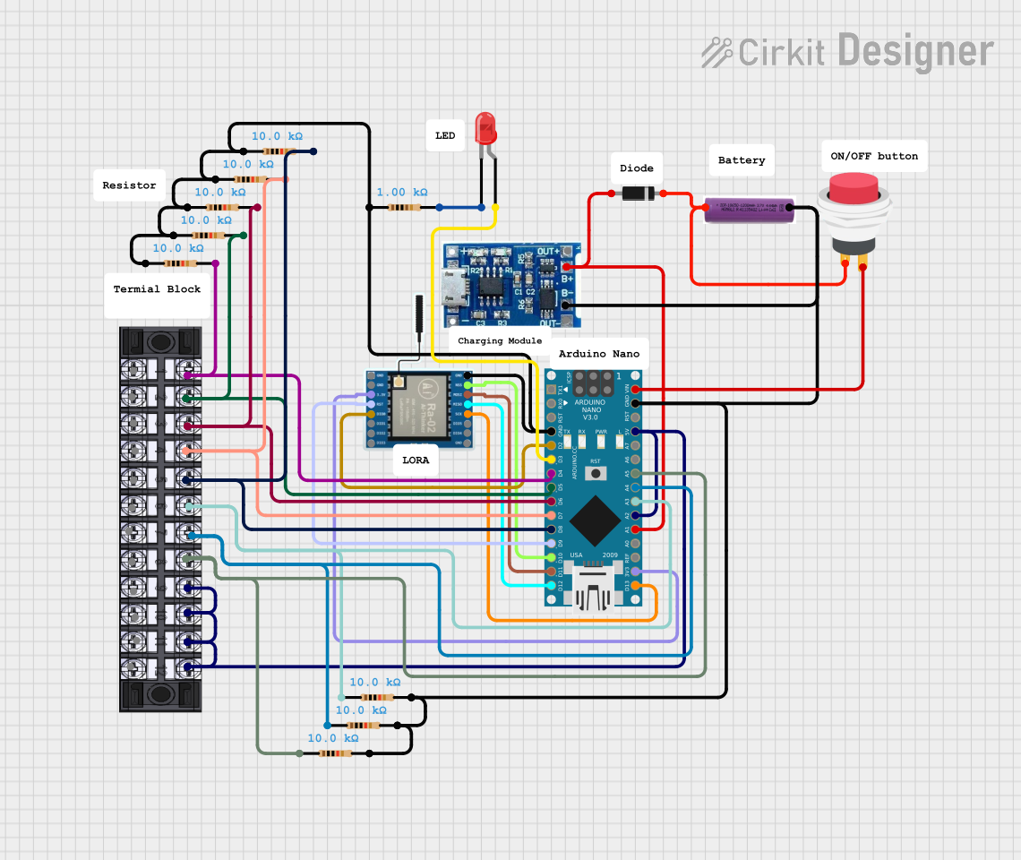
Circuit Documentation
Summary
This document provides a detailed overview of a circuit that integrates an Arduino Nano microcontroller with a LoRa Ra-02 SX1278 module, a LiPo battery charger module, a 3.7V battery, an LED, a push switch, a diode, and several resistors. The circuit is designed to receive data via LoRa communication and display it on an LCD screen. The Arduino Nano is programmed to handle the LoRa communication and display the received data.
Component List
Arduino Nano
- Description: A small, complete, and breadboard-friendly board based on the ATmega328P.
- Pins: D1/TX, D0/RX, RESET, GND, D2, D3, D4, D5, D6, D7, D8, D9, D10, D11/MOSI, D12/MISO, VIN, 5V, A7, A6, A5, A4, A3, A2, A1, A0, AREF, 3V3, D13/SCK
LoRa Ra-02 SX1278
- Description: A long-range transceiver module for LoRa communication.
- Pins: GND, NSS, MOSI, MISO, SCK, D105, DI04, 3.3V, RST, DI00, DI01, D102, DI03
LiPo Battery Charger Module
- Description: A module for charging LiPo batteries.
- Pins: B-, B+, OUT-, OUT+
3.7V Battery
- Description: A rechargeable lithium polymer battery.
- Pins: +, -
2-Pin Push Switch
- Description: A simple push-button switch.
- Pins: Input +, Output +
LED: Two Pin (Red)
- Description: A red LED with two pins.
- Pins: cathode, anode
Diode
- Description: A semiconductor device that allows current to flow in one direction.
- Pins: cathode, anode
Resistors
- Description: Various resistors used for current limiting and voltage division.
- Pins: pin1, pin2
- Properties:
- Resistance: 1000 Ohms
- Resistance: 10000 Ohms (multiple instances)
Terminal Block 12
- Description: A terminal block with 12 connection points.
- Pins: T1, T2, T3, T4, T5, T6, T7, T8, T9, T10, T11, T12, L1, L2, L3, L4, L5, L6, L7, L8, L9, L10, L11, L12
Wiring Details
Arduino Nano
- GND: Connected to GND of LoRa Ra-02 SX1278, pin1 of multiple resistors, GND of 3.7V battery, B- of LiPo battery charger module.
- D2: Connected to DI00 of LoRa Ra-02 SX1278.
- D3: Connected to anode of LED (Red).
- D4: Connected to pin2 of a resistor, T1 of Terminal Block 12.
- D5: Connected to pin2 of a resistor, T2 of Terminal Block 12.
- D6: Connected to pin2 of a resistor, T3 of Terminal Block 12.
- D7: Connected to pin2 of a resistor, T4 of Terminal Block 12.
- D8: Connected to pin2 of a resistor, T5 of Terminal Block 12.
- D9: Connected to RST of LoRa Ra-02 SX1278.
- D10: Connected to NSS of LoRa Ra-02 SX1278.
- D11/MOSI: Connected to MOSI of LoRa Ra-02 SX1278.
- D12/MISO: Connected to MISO of LoRa Ra-02 SX1278.
- VIN: Connected to Output + of 2-Pin Push Switch.
- 5V: Connected to A2 of Arduino Nano, T11, T12, T9, T10 of Terminal Block 12.
- A5: Connected to T8 of Terminal Block 12, pin1 of a resistor.
- A4: Connected to T7 of Terminal Block 12, pin1 of a resistor.
- A3: Connected to T6 of Terminal Block 12, pin1 of a resistor.
- A1: Connected to anode of Diode, B+ of LiPo battery charger module.
- 3V3: Connected to 3.3V of LoRa Ra-02 SX1278.
- D13/SCK: Connected to SCK of LoRa Ra-02 SX1278.
LoRa Ra-02 SX1278
- GND: Connected to GND of Arduino Nano.
- NSS: Connected to D10 of Arduino Nano.
- MOSI: Connected to D11/MOSI of Arduino Nano.
- MISO: Connected to D12/MISO of Arduino Nano.
- SCK: Connected to D13/SCK of Arduino Nano.
- 3.3V: Connected to 3V3 of Arduino Nano.
- RST: Connected to D9 of Arduino Nano.
- DI00: Connected to D2 of Arduino Nano.
LiPo Battery Charger Module
- B-: Connected to GND of Arduino Nano.
- B+: Connected to anode of Diode, A1 of Arduino Nano.
3.7V Battery
- -: Connected to GND of Arduino Nano.
- +: Connected to cathode of Diode, Input + of 2-Pin Push Switch.
2-Pin Push Switch
- Input +: Connected to + of 3.7V Battery.
- Output +: Connected to VIN of Arduino Nano.
LED: Two Pin (Red)
- anode: Connected to D3 of Arduino Nano.
- cathode: Connected to pin2 of a resistor.
Diode
- cathode: Connected to + of 3.7V Battery.
- anode: Connected to B+ of LiPo Battery Charger Module, A1 of Arduino Nano.
Resistors
- pin1: Connected to GND of Arduino Nano (multiple instances).
- pin2: Connected to various pins of Arduino Nano and Terminal Block 12.
Terminal Block 12
- T1: Connected to D4 of Arduino Nano, pin2 of a resistor.
- T2: Connected to D5 of Arduino Nano, pin2 of a resistor.
- T3: Connected to D6 of Arduino Nano, pin2 of a resistor.
- T4: Connected to D7 of Arduino Nano, pin2 of a resistor.
- T5: Connected to D8 of Arduino Nano, pin2 of a resistor.
- T6: Connected to A3 of Arduino Nano, pin1 of a resistor.
- T7: Connected to A4 of Arduino Nano, pin1 of a resistor.
- T8: Connected to A5 of Arduino Nano, pin1 of a resistor.
- T9: Connected to 5V of Arduino Nano.
- T10: Connected to 5V of Arduino Nano.
- T11: Connected to 5V of Arduino Nano.
- T12: Connected to 5V of Arduino Nano.
Documented Code
#include <NewPing.h>
#include <LiquidCrystal_I2C.h>
#include <SPI.h>
#include <LoRa.h>

LiquidCrystal_I2C lcd(0x27, 16, 2);
String inString = "";
int counter = 0;

// Pinout on Arduino Nano
// LoRa module > Arduino: GND:GND, GND:GND, 3.3V:3.3V, RST:D9, DI00:D2, NSS:D10, MOSI:D11, MISO:D12, SCK:D13
// LCD 16x2 > Arduino: GND:GND, 5V:5V, SDA:A4, SCL:A5

void setup() {
  // initialize display
  lcd.init();
  lcd.backlight();
  lcd.setCursor(0, 0);

  // Begin Serial communication at a baudrate of 9600:
  Serial.begin(9600);
  while (!Serial);
  Serial.println("LoRa Receiver");
  if (!LoRa.begin(433E6)) {
    Serial.println("Starting LoRa failed!");
    while (1);
  }
  LoRa.setSpreadingFactor(12);
  LoRa.setSignalBandwidth(62.5E3);
}

void loop() {
  int packetSize = LoRa.parsePacket();
  if (packetSize) {
    // received a packet
    Serial.println("");
    Serial.println(".................");
    Serial.println("Received packet: ");

    // read packet
    inString