Cirkit Designer
Your all-in-one circuit design IDE
Home /
Project Documentation
Arduino UNO and Sensor Shield Controlled 12V DC Motor with Encoder
Circuit Documentation
Summary
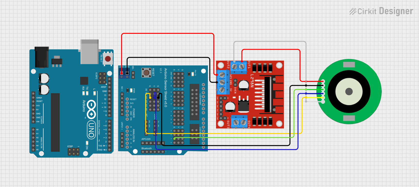
This document provides a detailed overview of a circuit that includes an Arduino Sensor Shield v5.0, an L298N DC motor driver, a 12V DC Motor Encoder, and an Arduino UNO. The circuit is designed to control a DC motor with encoder feedback, interfacing through the Arduino Sensor Shield and the L298N motor driver. The Arduino UNO serves as the main microcontroller, running the control code.
Component List
Arduino Sensor Shield v5.0
- Description: A shield that provides easy connections for sensors and other peripherals to an Arduino board.
- Pins: VCC, SD-VCC, SD-GND, SD-D11, SD-D10, SD-D13, SD-D12, URF01-VCC, URF01-A0, URF01-A1, URF01-GND, GND, SEL1, SEL2, A0-SIG, A0-VCC, A0-GND, A1-SIG, A1-VCC, A1-GND, A2-SIG, A2-VCC, A2-GND, A3-SIG, A3-VCC, A3-GND, A4-SIG, A4-VCC, A4-GND, A5-SIG, A5-VCC, A5-GND, IIC-SCL, IIC-SDA, IIC-GND, IIC-VCC, COM-TX, COM-RX, COM-GND, COM-VCC, APC220-, APC220-D0, APC220-D1, APC220-VCC, APC220-GND, BLUETOOTH-3V3, BLUETOOTH-GND, BLUETOOTH-D0, BLUETOOTH-D1, BLUETOOTH-VCC, AREF-S, AREF-V, AREF-G, GND-S, GND-V, GND-G, 13-S, 13-V, 13-G, 12-S, 12-V, 12-G, 11-S, 11-V, 11-G, 10-S, 10-V, 10-G, 9-S, 9-V, 9-G, 8-S, 8-V, 8-G, 7-S, 7-V, 7-G, 6-S, 6-V, 6-G, 5-S, 5-V, 5-G, 4-S, 4-V, 4-G, 3-S, 3-V, 3-G, 2-S, 2-V, 2-G, 1-S, 1-V, 1-G, 0-S, 0-V, 0-G, ParallelLCD-VCC, ParallelLCD-D13, ParallelLCD-GND, ParallelLCD-D12, ParallelLCD-D2, ParallelLCD-D11, ParallelLCD-D3, ParallelLCD-D10, ParallelLCD-D4, ParallelLCD-D9, ParallelLCD-D5, ParallelLCD-D8, ParallelLCD-D6, ParallelLCD-D7, SerialLCD-D4, SerialLCD-VCC, SerialLCD-D3, SerialLCD-, SerialLCD-D2, SerialLCD-GND
L298N DC Motor Driver
- Description: A dual H-bridge motor driver that allows control of the speed and direction of two DC motors.
- Pins: OUT1, OUT2, 12V, GND, 5V, OUT3, OUT4, 5V-ENA-JMP-I, 5V-ENA-JMP-O, +5V-J1, +5V-J2, ENA, IN1, IN2, IN3, IN4, ENB
12V DC Motor Encoder
- Description: A DC motor with an integrated encoder for feedback on motor position and speed.
- Pins: M1, GND, A, 3.3V, B, M2
Arduino UNO
- Description: A microcontroller board based on the ATmega328P, used for a wide range of applications.
- Pins: UNUSED, IOREF, Reset, 3.3V, 5V, GND, Vin, A0, A1, A2, A3, A4, A5, SCL, SDA, AREF, D13, D12, D11, D10, D9, D8, D7, D6, D5, D4, D3, D2, D1, D0
Wiring Details
Arduino Sensor Shield v5.0
- VCC connected to 12V of L298N DC motor driver
- GND connected to GND of L298N DC motor driver
- A2-SIG connected to B of 12V DC Motor Encoder
- A2-VCC connected to 3.3V of 12V DC Motor Encoder
- A2-GND connected to GND of 12V DC Motor Encoder
- 1-S connected to A of 12V DC Motor Encoder
L298N DC Motor Driver
- 12V connected to VCC of Arduino Sensor Shield v5.0
- GND connected to GND of Arduino Sensor Shield v5.0
- OUT1 connected to M1 of 12V DC Motor Encoder
- OUT2 connected to M2 of 12V DC Motor Encoder
12V DC Motor Encoder
- M1 connected to OUT1 of L298N DC motor driver
- M2 connected to OUT2 of L298N DC motor driver
- B connected to A2-SIG of Arduino Sensor Shield v5.0
- 3.3V connected to A2-VCC of Arduino Sensor Shield v5.0
- GND connected to A2-GND of Arduino Sensor Shield v5.0
- A connected to 1-S of Arduino Sensor Shield v5.0
Arduino UNO
- No direct connections specified in the provided net list.
Documented Code
sketch.ino
void setup() {
  // put your setup code here, to run once:

}

void loop() {
  // put your main code here, to run repeatedly:

}
documentation.txt
This document provides a comprehensive overview of the circuit, including the components used, their connections, and the code running on the Arduino UNO.