
Arduino UNO Bluetooth-Controlled Robot with Obstacle Avoidance and LED Indicators
View and Edit Project In Cirkit Designer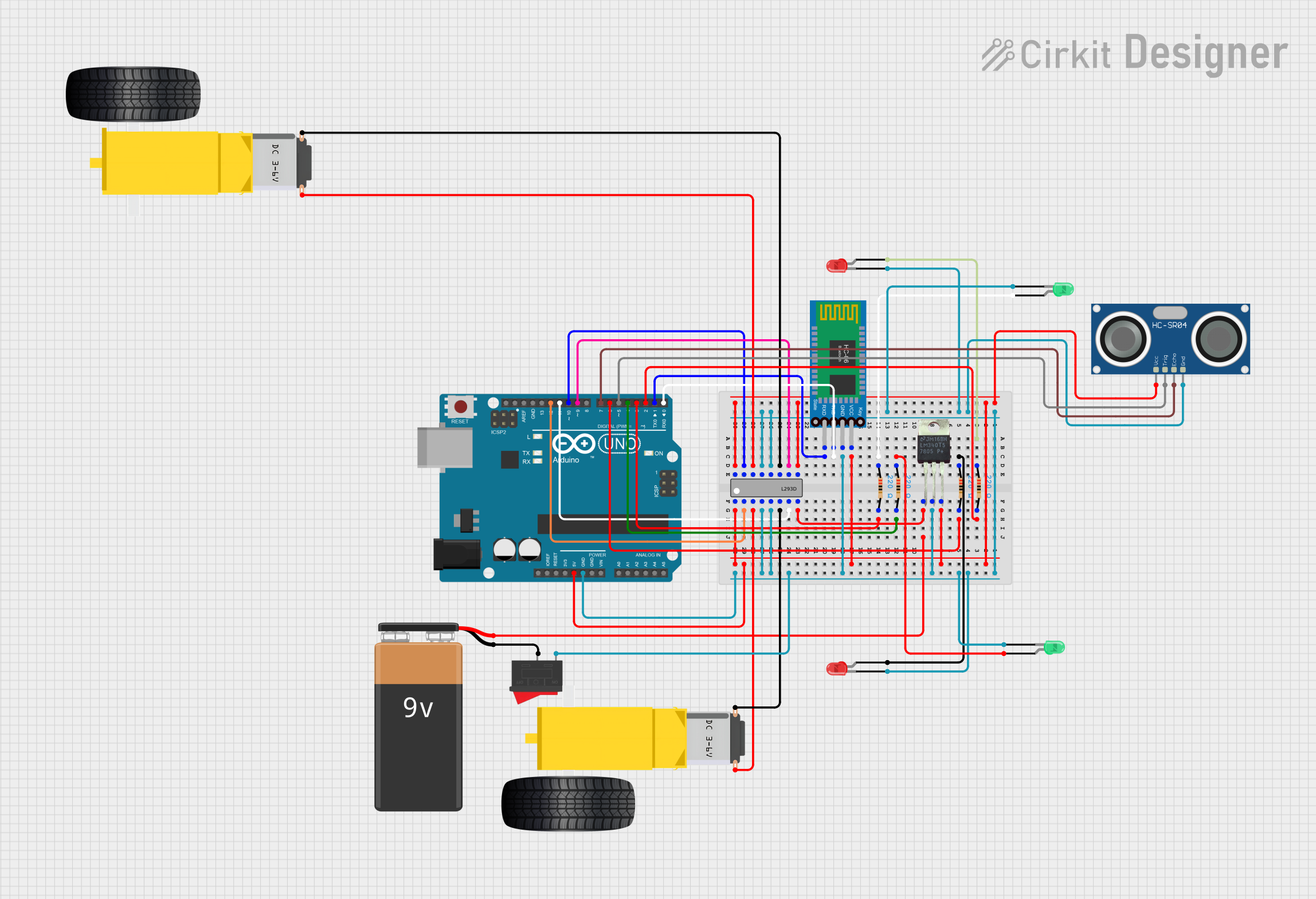
Circuit Documentation
Summary
The circuit in question appears to be a robotic vehicle with Bluetooth control, obstacle detection, and visual indicators. It is powered by a 9V battery and uses an Arduino UNO as the central microcontroller. The circuit includes motor control via an L293D driver, distance measurement using an HC-SR04 ultrasonic sensor, and Bluetooth communication through an HC-06 module. Visual feedback is provided by green and red LEDs, which are current-limited by resistors. A voltage regulator (LM340T5 7805) ensures stable power supply to the components.
Component List
Microcontroller
- Arduino UNO: A microcontroller board based on the ATmega328P, featuring digital and analog I/O pins.
Power Supply
- 9V Battery: Provides power to the circuit.
- LM340T5 7805: A voltage regulator that outputs a stable 5V from the input supply.
Actuators
- Gearmotor DC Wheels (left and right): Provide locomotion for the robotic vehicle.
- L293D: A motor driver IC that controls the direction and speed of DC motors.
Sensors
- HC-SR04 Ultrasonic Sensor: Measures distance by emitting ultrasonic waves and timing their return after reflecting off objects.
Communication
- Bluetooth HC-06: A Bluetooth module for wireless communication, typically used for remote control.
Indicators
- LEDs (green and red): Visual indicators for the status and actions of the robotic vehicle.
- Resistors (220 Ohms): Limit current to the LEDs to prevent damage.
Control
- Rocker Switch: Acts as a power switch for the circuit.
Wiring Details
Arduino UNO
- Digital pins D2, D3, D4, D5, D6, D7, D9, D10, D11, and D12 are used for controlling LEDs, motors, and the ultrasonic sensor.
- The 5V and GND pins provide power to the circuit components.
- Pins D0 (RX) and D1 (TX) are used for Bluetooth communication.
LEDs
- Each LED has an anode connected to a digital pin on the Arduino through a 220 Ohm resistor.
- The cathodes of all LEDs are connected to the ground.
Gearmotors
- Controlled by the L293D motor driver, with inputs from the Arduino and outputs to the motors.
HC-SR04 Ultrasonic Sensor
- VCC and GND pins are connected to the power supply.
- TRIG and ECHO pins are connected to digital pins D5 and D7 on the Arduino, respectively.
Bluetooth HC-06
- VCC and GND pins are connected to the power supply.
- TXD and RXD pins are connected to pins D0 and D1 on the Arduino for serial communication.
L293D Motor Driver
- Enable and input pins are connected to various digital pins on the Arduino for motor control.
- Output pins are connected to the gearmotors.
LM340T5 7805 Voltage Regulator
- Input from the 9V battery, output provides a regulated 5V supply to the circuit.
Rocker Switch
- Connected in series with the 9V battery to control power to the circuit.
Documented Code
Arduino Sketch (sketch.ino)
#include <Wire.h>
#include <LiquidCrystal_I2C.h>

#define TRIGPIN 5
#define ECHOPIN 7

// Initialization
int m1a = 9;   // Motor 1, Arduino pin 10 to L293B pin 15.
int m1b = 10;  // Motor 1, Arduino pin 9 to L293B pin 10.
int m2a = 11;  // Motor 2, Arduino pin 12 to L293B pin 2.
int m2b = 12;  // Motor 2, Arduino pin 11 to L293B pin 7.
char val;
bool ready = false;

int VerdDreta = 3;
int VerdEsquerra = 4;
int VermellDreta = 6;
int VermellEsquerra = 2;

LiquidCrystal_I2C lcd(0X27,16,2);

// Eyes definition (custom LCD characters omitted for brevity)

// Setup method
void setup() {
  // Pin configuration
  pinMode(m1a, OUTPUT);
  pinMode(m1b, OUTPUT);
  pinMode(m2a, OUTPUT);
  pinMode(m2b, OUTPUT);

  pinMode(VerdDreta, OUTPUT);
  pinMode(VerdEsquerra, OUTPUT);
  pinMode(VermellDreta, OUTPUT);
  pinMode(VermellEsquerra, OUTPUT);

  pinMode(TRIGPIN, OUTPUT);
  pinMode(ECHOPIN, INPUT);

  // LCD initialization
  lcd.init();
  lcd.backlight();
  lcd.clear();
  lcd.setCursor(2,0);
  lcd.print("ANIOL CASTANY");
  lcd.setCursor(6,1);
  lcd.print("TDR");

  // Serial communication start
  Serial.begin(9600);
}

// Main loop
void loop() {
  int obstacle = 0;

  // Bluetooth communication
  if (Serial.available() > 0)  {
    val = Serial.read();
    Serial.println(val);

    lcd.clear();
    lcd.setCursor(15,1);
    lcd.print(val);
  }

  // Movement commands
  if (val == 'F' && ready) {
    // Forward if no obstacle
    obstacle = measure_mm();

    if ((obstacle > 0) && (obstacle < 200)) {
      stop_and_reverse();
    } else {
      MotorsForward();
    }

    delay(50);

  }
  // Other movement commands omitted for brevity
}

// Motor control functions (omitted for brevity)

// Distance measurement function
int measure_mm() {
  digitalWrite(TRIGPIN, LOW);
  delayMicroseconds(2);
  digitalWrite(TRIGPIN, HIGH);
  delayMicroseconds(10);
  digitalWrite(TRIGPIN, LOW);
  float time = pulseIn(ECHOPIN, HIGH);
  int distance = int(time * 0.343 / 2);
  return (distance);
}

// LCD eye patterns (omitted for brevity)
Additional Documentation (documentation.txt)
Material List

Base:
+ Arduino UNO
+ Medium Breadboard
+ 9V Battery
+ Switch
+ Wires

Mobility:
+ 2 DC Motors with wheels
+ L293D Controller
+ LM340T5

Distance Sensor:
+ HC-SR04 Ultrasonic Sensor

Control:
+ Bluetooth HC-05 Controller

Display:
+ LCD-I2C Screen

Lights:
+ 4 resistors
+ 2 Green LEDs
+ 2 Red LEDs

Chassis:
+ Lower Chassis
+ Central Chassis
+ Front Upper Chassis
+ Rear Upper Chassis
+ Front Wheel
+ Screws
This documentation provides an overview of the circuit, including the components used, their wiring, and the embedded code that controls the robotic vehicle. The code includes functions for motor control, Bluetooth communication, and distance measurement, as well as custom LCD character definitions for visual feedback.