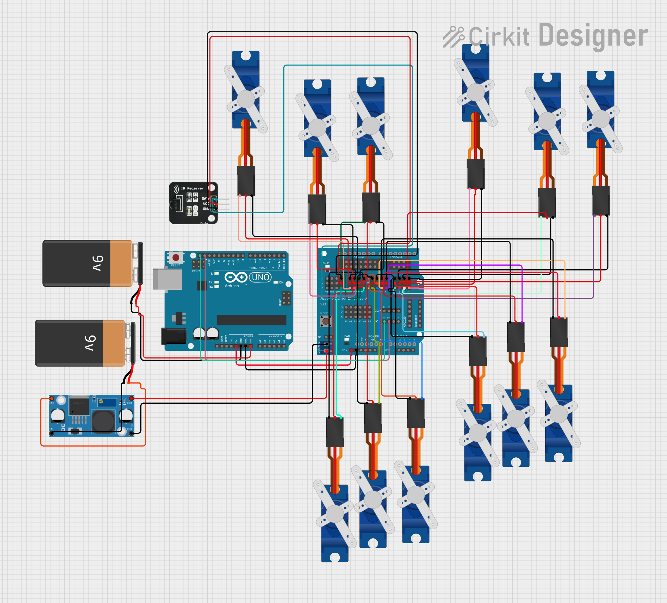
Arduino UNO Controlled Quadruped Spider Robot with IR Remote

Circuit Documentation
Summary
This circuit is designed to control a quadruped spider robot with multiple servo motors, using an Arduino UNO as the main microcontroller. The Arduino UNO receives commands from an IR receiver and drives twelve Tower Pro SG90 servos to move the robot in various directions or perform actions such as saying hello. The servos are powered by a 5V supply from a buck converter, which steps down the voltage from a 9V battery. The Arduino Sensor Shield v5.0 is used to facilitate easy connections between the Arduino UNO and the servos.
Component List
Microcontroller
- Arduino UNO: A microcontroller board based on the ATmega328P, with digital and analog I/O pins.
Power Supply
- 9V Batteries (x2): Provide power to the circuit.
- LM2956 Buck Converter DC-DC: Steps down the voltage from 9V to 5V to power the servos.
Actuators
- Tower Pro SG90 Servos (x12): Small and lightweight servos used for actuating the robot's legs.
Sensors
- IR Receiver: Receives infrared signals from a remote control to command the robot.
Shields
- Arduino Sensor Shield v5.0: An expansion board that allows for easy connection of sensors and actuators to the Arduino UNO.
Wiring Details
Arduino UNO
- 5V to Sensor Shield SD-VCC
- GND to 9V Battery (-) and Sensor Shield SD-GND
- Vin to 9V Battery (+)
- SCL to Sensor Shield IIC-SCL
- SDA to Sensor Shield IIC-SDA
Arduino Sensor Shield v5.0
- VCC from LM2956 Buck Converter OUT+
- GND from LM2956 Buck Converter OUT-
- Various Signal Pins (S) connected to corresponding servo Signal pins
- Various +5V Pins (V) connected to corresponding servo +5V pins
- Various GND Pins (G) connected to corresponding servo GND pins
LM2956 Buck Converter DC-DC
- IN+ to 9V Battery (+)
- IN- to 9V Battery (-)
IR Receiver
- DATA to Sensor Shield 12-S
- VCC to Sensor Shield 12-V
- GND to Sensor Shield 12-G
Tower Pro SG90 Servos
- Signal to corresponding Sensor Shield Signal pins
- +5V to corresponding Sensor Shield +5V pins
- GND to corresponding Sensor Shield GND pins
Documented Code
/*
 * This Arduino sketch controls a quadruped spider robot with 3 servo motors
 * per leg, using an IR receiver to interpret commands from a remote control.
 * The robot moves forward if the up arrow is pressed, sideways if the left or
 * right arrow is pressed, and says hello with one leg if the number 1 is
 * pressed.
 */

#include <Servo.h>
#include <IRremote.h>

#define FORWARD 0xFF629D
#define LEFT 0xFF22DD
#define RIGHT 0xFFC23D
#define HELLO 0xFF6897

const int RECV_PIN = 12;
IRrecv irrecv(RECV_PIN);
decode_results results;

Servo servos[12];

void setup() {
  irrecv.enableIRIn();
  for (int i = 0; i < 12; i++) {
    servos[i].attach(i);
  }
}

void loop() {
  if (irrecv.decode(&results)) {
    switch (results.value) {
      case FORWARD:
        moveForward();
        break;
      case LEFT:
        moveLeft();
        break;
      case RIGHT:
        moveRight();
        break;
      case HELLO:
        sayHello();
        break;
    }
    irrecv.resume();
  }
}

void moveForward() {
  for (int i = 0; i < 12; i++) {
    servos[i].write(90);
  }
  delay(1000);
  for (int i = 0; i < 12; i++) {
    servos[i].write(0);
  }
  delay(1000);
}

void moveLeft() {
  for (int i = 0; i < 6; i++) {
    servos[i].write(90);
  }
  delay(1000);
  for (int i = 0; i < 6; i++) {
    servos[i].write(0);
  }
  delay(1000);
}

void moveRight() {
  for (int i = 6; i < 12; i++) {
    servos[i].write(90);
  }
  delay(1000);
  for (int i = 6; i < 12; i++) {
    servos[i].write(0);
  }
  delay(1000);
}

void sayHello() {
  servos[0].write(90);
  delay(1000);
  servos[0].write(0);
  delay(1000);
}
This code is designed to be uploaded to the Arduino UNO microcontroller. It initializes an array of Servo objects and an IR receiver. In the setup function, it attaches the servos to the corresponding pins and enables the IR receiver. The loop function listens for IR commands and calls the appropriate movement functions: moveForward, moveLeft, moveRight, or sayHello. Each function controls the servos to perform the desired action.