Cirkit Designer
Your all-in-one circuit design IDE
Home /
Project Documentation
Arduino UNO CNC Robot with Ultrasonic Sensor and MPU6050
Circuit Documentation
Summary
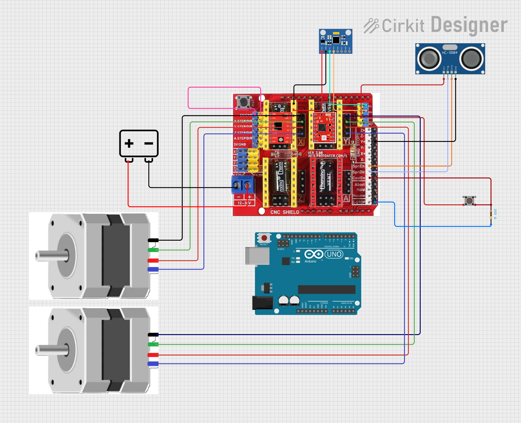
This document provides a detailed overview of a circuit designed to control a robot using an Arduino UNO, CNC Shield V3, stepper motors, and various sensors. The circuit includes connections for motor drivers, an ultrasonic sensor, an accelerometer/gyroscope, and a pushbutton. The Arduino UNO is programmed to control the robot's movements based on sensor inputs.
Component List
NEMA23 Stepper Motor
- Pins: A+, A-, B+, B-
- Description: High-torque stepper motor used for precise control of the robot's movements.
A988 Driver
- Pins: VMOT, GND, 2B, 2A, 1A, 1B, VDD, EN, MS1, MS2, MS3, RST, SLP, STEP, DIR
- Description: Stepper motor driver used to control the NEMA23 stepper motors.
Arduino UNO
- Pins: UNUSED, IOREF, Reset, 3.3V, 5V, GND, Vin, A0, A1, A2, A3, A4, A5, SCL, SDA, AREF, D13, D12, D11, D10, D9, D8, D7, D6, D5, D4, D3, D2, D1, D0
- Description: Microcontroller used to control the entire circuit and execute the embedded code.
CNC Shield V3 Engraving Machine Expansion Board
- Pins: EN, GND, x.Step, DIR, Y.Step, Z.Step, A.Step, 5V, COM, V+, End Stop X-, End Stop Z+, End Stop Z-, End Stop Y+, End Stop Y-, SpnEN, SpnDir, CoolEn, Abort, Hold, Resume, E-Stop, Y.Motor A+, Y.Motor A-, Y.Motor B+, Y.Motor B-, RST, SDA, SCL, RX, TX, 3V3, X.Motor A+, X.Motor A-, X.Motor B+, X.Motor B-, Z.Motor A+, Z.Motor A-, Z.Motor B+, Z.Motor B-, A.Motor A+, A.Motor A-, A.Motor B+, A.Motor B-, Enable, MS1, MS2, MS3, RESET, Sleep, Step, Direction, VDD, 1B, 1A, 2A, 2B, VMOT, M0, M1, M2, d12, A Drive Step and Direction, Z Drive Module Setp D4, Y Drive Module Setp D3, X Drive Module Setp D2, Set X Drive Module Dir D5, Set Y Drive Module Dir D6, Set Z Drive Module DIR d7, D13
- Description: Expansion board used to interface the Arduino UNO with stepper motor drivers and other components.
HC-SR04 Ultrasonic Sensor
- Pins: VCC, TRIG, ECHO, GND
- Description: Ultrasonic sensor used to measure distance to obstacles.
MPU6050 Accelerometer + Gyroscope (Wokwi Compatible)
- Pins: INT, AD0, XCL, XDA, SDA, SCL, GND, VCC
- Description: Sensor used to measure acceleration and angular velocity.
A4988 Stepper Motor Driver (Red)
- Pins: ENABLE, MS1, MS2, MS3, RESET, SLEEP, STEP, DIR, VMOT, GND, 2B, 2A, 1A, 1B, VDD
- Description: Stepper motor driver used to control the NEMA23 stepper motors.
Resistor
- Pins: pin1, pin2
- Description: 200 Ohms resistor used for current limiting.
Pushbutton
- Pins: Pin 3 (out), Pin 4 (out), Pin 1 (in), Pin 2 (in)
- Description: Pushbutton used for user input.
12v Battery
- Pins: -, +
- Description: Power source for the circuit.
Wiring Details
NEMA23 Stepper Motor
- A+ connected to Y.Motor A+ on CNC Shield V3
- A- connected to Y.Motor A- on CNC Shield V3
- B+ connected to Y.Motor B+ on CNC Shield V3
- B- connected to Y.Motor B- on CNC Shield V3
A988 Driver
- VMOT connected to power supply
- GND connected to ground
- 2B connected to stepper motor
- 2A connected to stepper motor
- 1A connected to stepper motor
- 1B connected to stepper motor
- VDD connected to 5V
- EN connected to enable pin
- MS1 connected to microstepping pin
- MS2 connected to microstepping pin
- MS3 connected to microstepping pin
- RST connected to reset pin
- SLP connected to sleep pin
- STEP connected to step pin
- DIR connected to direction pin
Arduino UNO
- D2 connected to PUL1_PIN (Stepper Motor 1 Pulse)
- D5 connected to DIR1_PIN (Stepper Motor 1 Direction)
- D3 connected to PUL2_PIN (Stepper Motor 2 Pulse)
- D6 connected to DIR2_PIN (Stepper Motor 2 Direction)
- D4 connected to BUTTON_PIN (Pushbutton)
CNC Shield V3 Engraving Machine Expansion Board
- EN connected to GND
- COM connected to - on 12v Battery
- V+ connected to + on 12v Battery
- GND connected to GND on HC-SR04 Ultrasonic Sensor
- SpnEN connected to ECHO on HC-SR04 Ultrasonic Sensor
- SpnDir connected to TRIG on HC-SR04 Ultrasonic Sensor
- CoolEn connected to pin1 on Resistor and Pin 2 (in) on Pushbutton
- 5V connected to Pin 1 (in) on Pushbutton and VCC on HC-SR04 Ultrasonic Sensor
- SDA connected to SDA on MPU6050 Accelerometer + Gyroscope
- SCL connected to SCL on MPU6050 Accelerometer + Gyroscope
- GND connected to GND on MPU6050 Accelerometer + Gyroscope
- VDD connected to VCC on MPU6050 Accelerometer + Gyroscope
HC-SR04 Ultrasonic Sensor
- GND connected to GND on CNC Shield V3
- ECHO connected to SpnEN on CNC Shield V3
- TRIG connected to SpnDir on CNC Shield V3
- VCC connected to 5V on CNC Shield V3
MPU6050 Accelerometer + Gyroscope
- SDA connected to SDA on CNC Shield V3
- SCL connected to SCL on CNC Shield V3
- GND connected to GND on CNC Shield V3
- VCC connected to VDD on CNC Shield V3
Resistor
- pin1 connected to CoolEn on CNC Shield V3 and Pin 2 (in) on Pushbutton
- pin2 connected to GND on CNC Shield V3
Pushbutton
- Pin 1 (in) connected to 5V on CNC Shield V3
- Pin 2 (in) connected to CoolEn on CNC Shield V3 and pin1 on Resistor
12v Battery
- - connected to COM on CNC Shield V3
- + connected to V+ on CNC Shield V3
Code Documentation
/*
 * @Author: MacKhoi Hoang
 * @Date: 12-19-24
 * @Description: SciOly Robot Tour
 * HISTORY:
 * VERSION  1.1-  Initial release the robot with step motor, using CNC Shield V3.0 + A4988 motor drive
 */

#include <SoftwareSerial.h>
#include <avr/wdt.h>
#include <stdint.h>
#include <stdio.h>
#include <string.h>
#include "Serial.h"
#include "LED.h"
#include "ULTRASONIC.h"
#include "MotorControl.h"
#include "Key.h"
#include "MPU6050_getdata.h"

#define PUL1_PIN    2
#define DIR1_PIN    5
#define PUL2_PIN    3