
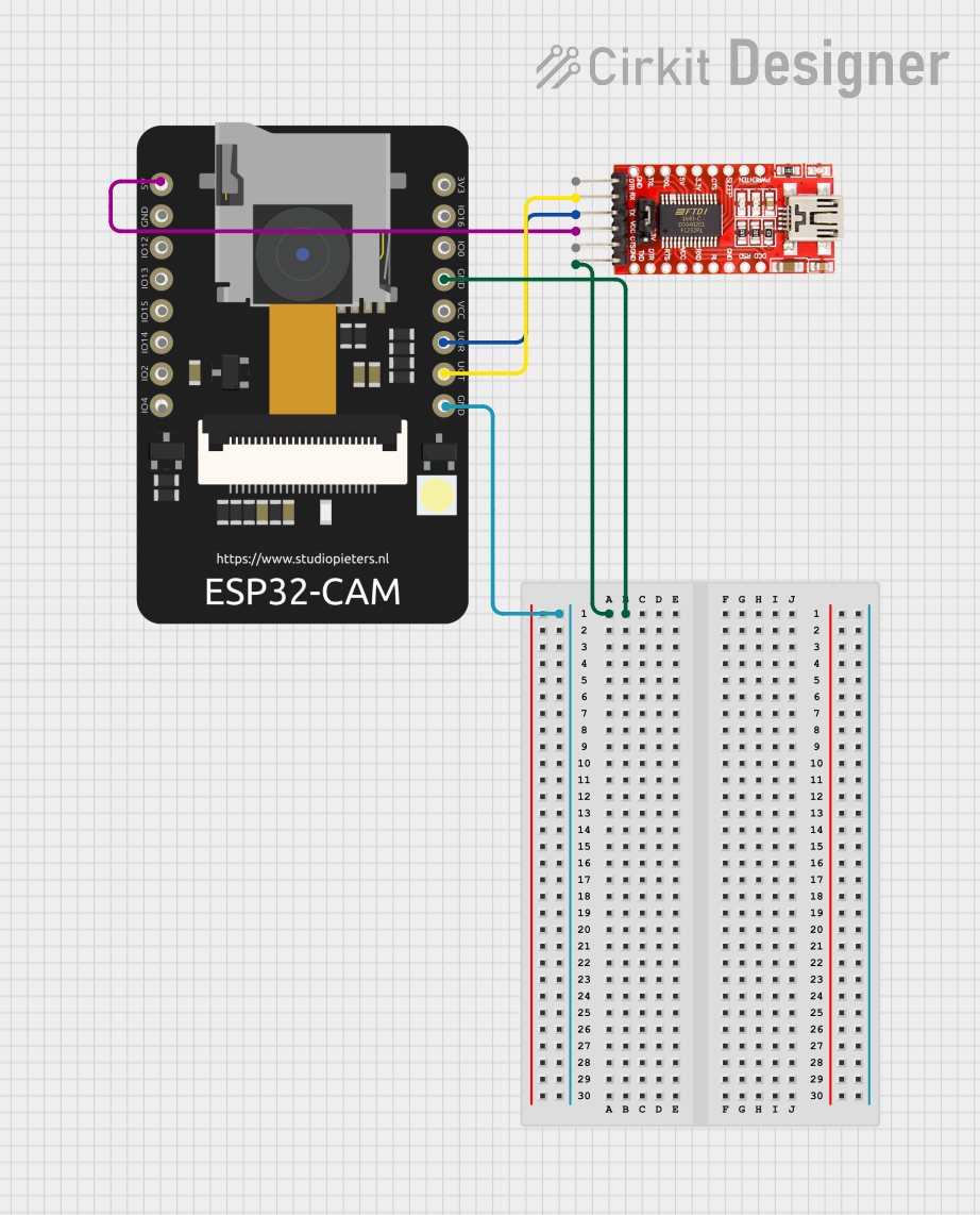
Circuit Documentation
Summary of the Circuit
This circuit consists of an ESP32 CAM module interfaced with an FTDI Programmer. The ESP32 CAM is a small camera module with Wi-Fi capabilities that can be used for various IoT applications. The FTDI Programmer is used to program the ESP32 CAM module via a serial interface. The circuit is designed to establish a serial communication link between the ESP32 CAM and the FTDI Programmer for programming and debugging purposes.
Component List
ESP32 CAM
- Description: A small-sized camera module with Wi-Fi capabilities, suitable for IoT applications.
- Pins: 5V, GND, GPIO12, GPIO13, GPIO15, GPIO14, GPIO2, GPIO4, 3.3V, GPIO16, GPIO0, 3.3V / 5V / P_OUT, GPIO3 / RX, GPIO1 / TX
FTDI Programmer
- Description: A USB to serial converter used to program devices with a UART interface.
- Pins: DTR, RX, TX, VCC, CTS, GND
Wiring Details
ESP32 CAM
- 5V: Connected to the VCC pin of the FTDI Programmer to provide power.
- GND: Connected to the GND pin of the FTDI Programmer to establish a common ground.
- GPIO3 / RX: Connected to the TX pin of the FTDI Programmer to receive data.
- GPIO1 / TX: Connected to the RX pin of the FTDI Programmer to transmit data.
FTDI Programmer
- VCC: Connected to the 5V pin of the ESP32 CAM to provide power.
- GND: Connected to the GND pin of the ESP32 CAM to establish a common ground.
- TX: Connected to the GPIO3 / RX pin of the ESP32 CAM to transmit data.
- RX: Connected to the GPIO1 / TX pin of the ESP32 CAM to receive data.
Documented Code
No code has been provided for the microcontrollers in the circuit. If code becomes available, it should be documented in this section with appropriate comments and explanations for each function and routine.