
Arduino UNO Controlled AC Motor Speed Regulator with Opto-Isolation and Pushbutton Interface
View and Edit Project In Cirkit Designer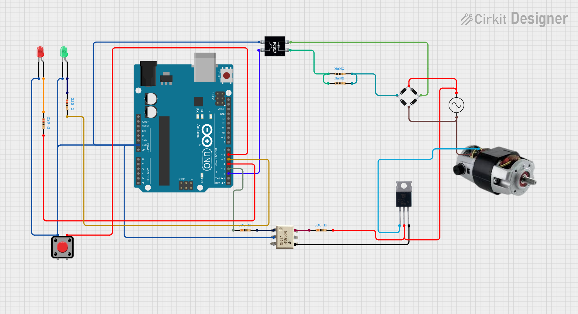
Circuit Documentation
Summary
This document provides a detailed overview of a circuit that includes a variety of components such as an Arduino UNO microcontroller, LEDs, a pushbutton, optoisolators, a bridge rectifier, resistors, an AC supply, a triac, and a universal motor. The circuit appears to be designed for controlling the universal motor using the Arduino UNO, with input from a pushbutton and feedback through LEDs. The optoisolators and triac are likely used for isolating the microcontroller from the high-voltage AC side and for controlling the power delivered to the motor.
Component List
Microcontroller
- Arduino UNO: A microcontroller board based on the ATmega328P, with digital input/output pins, analog inputs, and various power pins.
LEDs
- LED: Two Pin (red): A red light-emitting diode with an anode and cathode for indicating statuses or events.
- LED: Two Pin (green): A green light-emitting diode with an anode and cathode for indicating statuses or events.
Pushbutton
- Pushbutton: A simple switch mechanism for controlling some aspect of a machine or a process.
Optoisolators
- PC817: An optocoupler used to transfer electrical signals using light waves to provide coupling with electrical isolation between its input and output.
- MOC3041: An optoisolator with a triac driver output, typically used for interfacing with AC loads.
Bridge Rectifier
- Bridge rectifier: A device that converts an AC input into a DC output.
Resistors
- Resistor: A passive two-terminal electrical component that implements electrical resistance as a circuit element.
AC Supply
- Ac Supply: A power supply that provides AC voltage.
Triac
- BT139 600: A triac used for controlling the power flow to AC loads.
Universal Motor
- Universal motor AC: An electric motor that can operate on either AC or DC power.
Wiring Details
Arduino UNO
- Ground (GND) connected to the cathodes of the red and green LEDs, the cathode of the MOC3041, the emitter of the PC817, and Pin 1 of the pushbutton.
- Digital Pin 6 (D6) connected to Pin 4 of the pushbutton.
- Digital Pin 5 (D5) connected to a 220 Ohm resistor.
- Digital Pin 4 (D4) connected to a 220 Ohm resistor.
- Digital Pin 3 (D3) connected to a 330 Ohm resistor.
- Digital Pin 2 (D2) connected to the collector of the PC817.
LEDs
- Red LED: Anode connected to a 220 Ohm resistor.
- Green LED: Anode connected to a 330 Ohm resistor.
Pushbutton
- Pin 1 connected to the ground net.
- Pin 4 connected to Digital Pin 6 (D6) of the Arduino UNO.
PC817
- Anode connected to a resistor.
- Cathode connected to the bridge rectifier's source_out-.
- Collector connected to Digital Pin 2 (D2) of the Arduino UNO.
- Emitter connected to the ground net.
MOC3041
- TRIAC1 connected to a 330 Ohm resistor.
- TRIAC2 connected to the GATE of the BT139 600 triac.
- ANODE connected to a 330 Ohm resistor.
- CATHODE connected to the ground net.
Bridge Rectifier
- Source_in- connected to the N pin of the universal motor AC and the -ve pin of the AC supply.
- Source_out- connected to the cathode of the PC817.
- Source_out+ connected to resistors.
- Source_in+ connected to the +ve pin of the AC supply, a 330 Ohm resistor, and the MT2 pin of the BT139 600 triac.
Resistors
- Various resistors with values of 220 Ohms and 330 Ohms are used in the circuit, connected to LEDs, the Arduino UNO, and optoisolators.
AC Supply
- +ve connected to the source_in+ of the bridge rectifier.
- -ve connected to the source_in- of the bridge rectifier.
BT139 600
- MT1 connected to the P pin of the universal motor AC.
- MT2 connected to the source_in+ of the bridge rectifier.
- GATE connected to the TRIAC2 of the MOC3041.
Universal Motor AC
- N connected to the source_in- of the bridge rectifier.
- P connected to the MT1 of the BT139 600 triac.
Documented Code
Arduino UNO Microcontroller Code (sketch.ino)
void setup() {
  // put your setup code here, to run once:

}

void loop() {
  // put your main code here, to run repeatedly:

}
Note: The provided code is a template and does not contain any functional code. It needs to be populated with the logic required to control the circuit as per the design requirements.