ESP8266 NodeMCU with Multiple IR Sensors and Dual I2C LCD Displays
Circuit Documentation
Summary
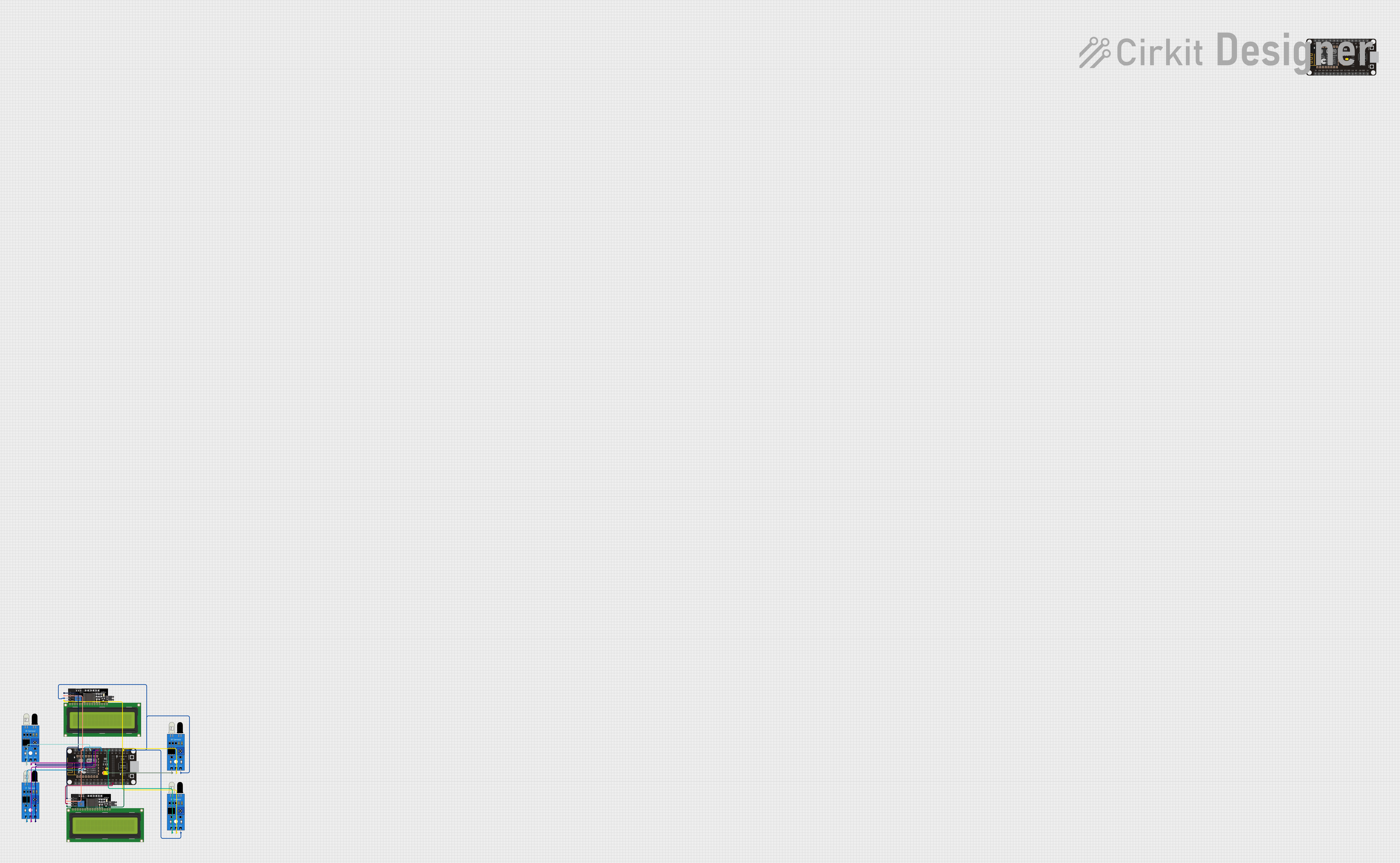
The circuit in question is designed to interface multiple IR sensors with an ESP8266 NodeMCU microcontroller and display data on two I2C LCD displays. The IR sensors are used to detect the presence or absence of objects, and their outputs are connected to the digital pins of the ESP8266 NodeMCU. The LCD displays are connected via the I2C bus to show information processed by the microcontroller. The ESP8266 NodeMCU is responsible for reading the sensor data, processing it, and updating the displays accordingly.
Component List
IR Sensors
- Component Name: IR Sensor
- Description: An infrared sensor capable of detecting object presence.
- Pins:
out,gnd,vcc
ESP8266 NodeMCU
- Component Name: ESP8266 NodeMCU
- Description: A Wi-Fi enabled microcontroller with digital I/O and I2C communication capabilities.
- Pins:
D0,D1,D2,D3,D4,3V3,GND,D5,D6,D7,D8,RX,TX,A0,RSV,SD3,SD2,SD1,CMD,SD0,CLK,EN,RST,VIN
LCD Display 16x4 I2C
- Component Name: LCD Display 16x4 I2C
- Description: A 16x4 character LCD display with an I2C interface.
- Pins:
SCL,SDA,VCC,GND
Wiring Details
IR Sensors
IR Sensor 1:
outconnected to ESP8266 NodeMCUD4gndconnected to ESP8266 NodeMCUGNDvccconnected to ESP8266 NodeMCU3V3
IR Sensor 2:
outconnected to ESP8266 NodeMCUD5gndconnected to ESP8266 NodeMCUGNDvccconnected to ESP8266 NodeMCU3V3
IR Sensor 3:
outconnected to ESP8266 NodeMCUD6gndconnected to ESP8266 NodeMCUGNDvccconnected to ESP8266 NodeMCU3V3
IR Sensor 4:
outconnected to ESP8266 NodeMCUD7gndconnected to ESP8266 NodeMCUGNDvccconnected to ESP8266 NodeMCU3V3
ESP8266 NodeMCU
- ESP8266 NodeMCU:
D4,D5,D6,D7connected to respective IR sensor outputsD1connected to LCD Display SCL linesD2connected to LCD Display SDA lines3V3connected to IR sensors and LCD Displays VCC linesGNDconnected to IR sensors and LCD Displays GND lines
LCD Display 16x4 I2C
LCD Display 1:
SCLconnected to ESP8266 NodeMCUD1SDAconnected to ESP8266 NodeMCUD2VCCconnected to ESP8266 NodeMCU3V3GNDconnected to ESP8266 NodeMCUGND
LCD Display 2:
SCLconnected to ESP8266 NodeMCUD1SDAconnected to ESP8266 NodeMCUD2VCCconnected to ESP8266 NodeMCU3V3GNDconnected to ESP8266 NodeMCUGND
Documented Code
No code has been provided for the microcontroller. The expected functionality would include initializing the I2C interface for communication with the LCD displays, setting up the digital pins for reading the IR sensor outputs, and implementing logic to process the sensor data and update the displays accordingly. Without the actual code, we cannot document specific functions or routines.