
Arduino-Controlled Motor Speed Regulation with Current Sensing and LCD Feedback
View and Edit Project In Cirkit Designer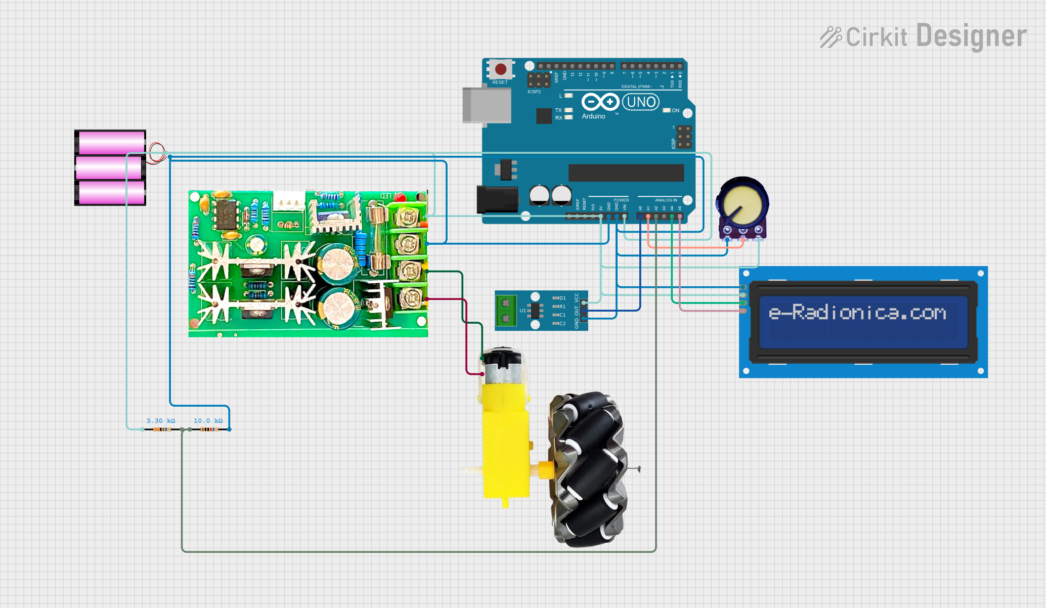
Circuit Documentation
Summary of the Circuit
This circuit is designed to control a motor using a PWM motor speed controller, with the speed being adjusted by a potentiometer. The Arduino UNO serves as the central processing unit, interfacing with an ACS712 current sensor to monitor current, a potentiometer to adjust motor speed, and an LCD screen to display information. The circuit is powered by a 12V battery, which supplies power to the Arduino, the motor controller, and other peripherals. The Arduino's analog inputs are used to read values from the current sensor and potentiometer, while the I2C communication protocol is used to interface with the LCD screen.
Component List
Arduino UNO
- Microcontroller board based on the ATmega328P
- It has 14 digital input/output pins, 6 analog inputs, a 16 MHz quartz crystal, a USB connection, a power jack, an ICSP header, and a reset button.
ACS712 Current Sensor 5A 20A 30A
- A hall effect-based current sensor capable of measuring both AC and DC currents.
PWM Motor Speed Controller
- A device that controls the speed of a motor by adjusting the pulse width of the voltage signal sent to the motor.
Motor and Wheels
- The actuator of the circuit, which converts electrical energy into mechanical motion.
Potentiometer
- A three-terminal resistor with a rotating contact that forms an adjustable voltage divider.
Battery 12V
- A 12-volt power source for the circuit.
Resistor (3300 Ohms)
- A passive two-terminal electrical component that implements electrical resistance as a circuit element.
Resistor (10000 Ohms)
- Another resistor with a higher resistance value.
LCD Screen 16x2 I2C
- A liquid crystal display capable of displaying 16 characters per line across 2 lines, with an I2C interface for communication.
Wiring Details
Arduino UNO
5VandGNDpins are connected to the power rails to supply power to the circuit.Vinis connected to the positive terminal of the 12V battery.A0is connected to the output of the ACS712 current sensor.A1is connected to the output of the potentiometer.A2is connected to a voltage divider network formed by the 3300 Ohm and 10000 Ohm resistors.A4(SDA) andA5(SCL) are connected to the corresponding SDA and SCL pins of the LCD screen.
ACS712 Current Sensor 5A 20A 30A
VCCandGNDare connected to the power rails.OUTis connected to theA0pin of the Arduino UNO.
PWM Motor Speed Controller
Power+andPower-are connected to the power rails.Motor+andMotor-are connected to the corresponding terminals of the motor.
Motor and Wheels
vccandGNDare connected to theMotor+andMotor-outputs of the PWM motor speed controller.
Potentiometer
VCCandGNDare connected to the power rails.Outputis connected to theA1pin of the Arduino UNO.
Battery 12V
+and-are connected to the power rails and theVinof the Arduino UNO.
Resistor (3300 Ohms)
- One end is connected to the
5Vpower rail, and the other end is connected to theA2pin of the Arduino UNO and to the 10000 Ohm resistor.
Resistor (10000 Ohms)
- One end is connected to the
GNDpower rail, and the other end is connected to theA2pin of the Arduino UNO and to the 3300 Ohm resistor.
LCD Screen 16x2 I2C
VCCandGNDare connected to the power rails.SDAandSCLare connected to theA4andA5pins of the Arduino UNO, respectively.
Documented Code
Arduino UNO Code (sketch.ino)
void setup() {
  // put your setup code here, to run once:

}

void loop() {
  // put your main code here, to run repeatedly:

}
This code is a template for the Arduino UNO and does not contain any functional code. It is expected that the user will fill in the setup() and loop() functions with code to initialize the circuit's components and define the main behavior of the circuit, respectively.