Cirkit Designer
Your all-in-one circuit design IDE
Home /
Project Documentation
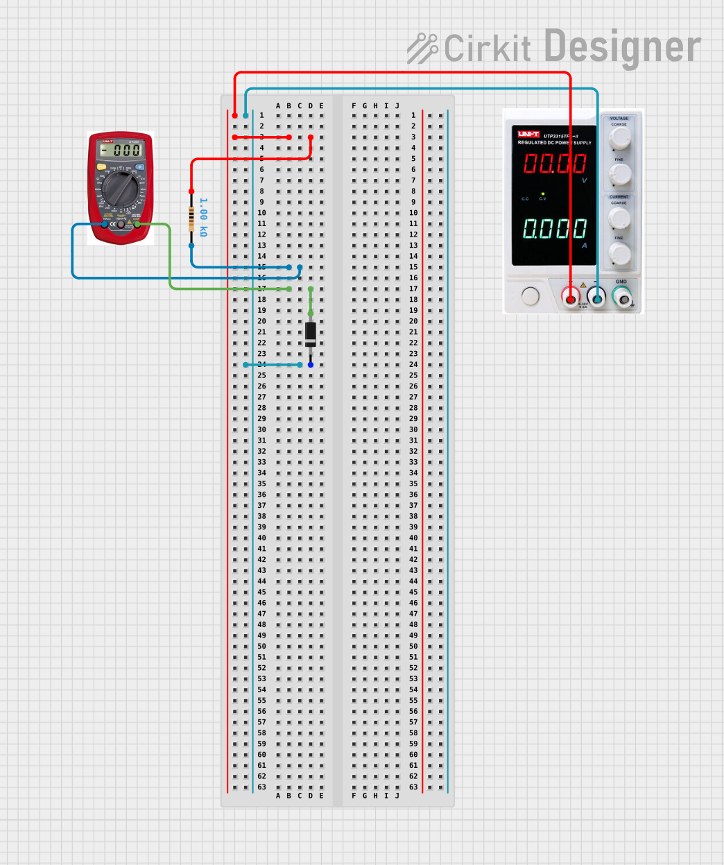
Resistor-Diode Circuit with Multimeter Current Measurement
Circuit Documentation
Summary of the Circuit
This circuit consists of a simple arrangement of a resistor, a power supply, a multimeter, and a diode. The power supply provides a voltage source that is connected through the resistor. The multimeter is used to measure the current flowing through the resistor. Additionally, a diode is included in the circuit, with its anode connected to the multimeter and its cathode connected to the negative terminal of the power supply. This setup could be used for basic current measurement and to demonstrate the directional flow of current through a diode.
Component List
Resistor
- Description: A resistor is a passive two-terminal electrical component that implements electrical resistance as a circuit element.
- Purpose: In this circuit, the resistor limits the current that flows through it.
- Properties:
- Resistance: 1000 Ohms
Power Supply
- Description: A power supply is an electrical device that supplies electric power to an electrical load.
- Purpose: It provides the necessary voltage to the circuit.
Multimeter
- Description: A multimeter is an instrument designed to measure electric current, voltage, and usually resistance, typically over several ranges of value.
- Purpose: In this circuit, it is used to measure the current flowing through the resistor.
Diode
- Description: A diode is a semiconductor device that allows current to flow in one direction only.
- Purpose: It ensures that current flows in the correct direction and prevents reverse current flow.
Wiring Details
Resistor
- Connections:
- One end is connected to the positive terminal of the Power Supply.
- The other end is connected to the "A" (Ampere) terminal of the Multimeter.
Power Supply
- Connections:
- The positive terminal is connected to one end of the Resistor.
- The negative terminal is connected to the cathode of the Diode.
- The ground terminal is not used in this circuit.
Multimeter
- Connections:
- The "A" terminal is connected to one end of the Resistor.
- The "COM" (Common) terminal is connected to the anode of the Diode.
- The "V" (Voltage) terminal is not used in this circuit.
Diode
- Connections:
- The anode is connected to the "COM" terminal of the Multimeter.
- The cathode is connected to the negative terminal of the Power Supply.
Documented Code
There is no embedded code provided for any microcontrollers in this circuit. Therefore, this section is not applicable to the current documentation.