Cirkit Designer
Your all-in-one circuit design IDE
Home /
Project Documentation
Arduino UNO Blinking LED Circuit
Circuit Documentation
Summary of the Circuit
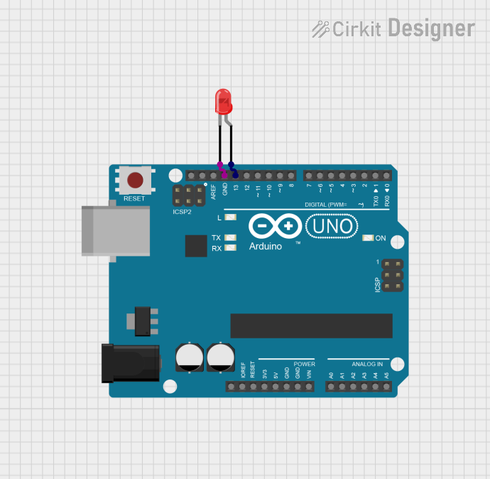
This circuit consists of an Arduino UNO microcontroller board and a two-pin red LED. The Arduino UNO is used to control the LED, turning it on and off at a regular interval. The LED is connected to one of the digital pins of the Arduino (pin D13) and to the ground (GND). The microcontroller is programmed to output a high voltage to the LED, causing it to light up, and then a low voltage to turn it off, creating a blinking effect.
Component List
Arduino UNO
- Description: A microcontroller board based on the ATmega328P.
- Pins: UNUSED, IOREF, Reset, 3.3V, 5V, GND, Vin, A0-A5, SCL, SDA, AREF, D0-D13
- Purpose: Acts as the central controller for the circuit, driving the LED and managing the timing for the blinking effect.
LED: Two Pin (red)
- Description: A basic red light-emitting diode.
- Pins: cathode, anode
- Purpose: Serves as the visual indicator that is controlled by the Arduino UNO.
Wiring Details
Arduino UNO
- GND is connected to the cathode of the LED.
- D13 is connected to the anode of the LED.
LED: Two Pin (red)
- Cathode is connected to the GND pin of the Arduino UNO.
- Anode is connected to the D13 pin of the Arduino UNO.
Documented Code
// Define the LED pin
int ledPin = 13;

// The setup function runs once when you press reset or power the board
void setup() {
  // Initialize digital pin 13 as an output.
  pinMode(ledPin, OUTPUT);
}

// The loop function runs over and over again forever
void loop() {
  digitalWrite(ledPin, HIGH);   // Turn the LED on (HIGH is the voltage level)
  delay(1000);                  // Wait for a second
  digitalWrite(ledPin, LOW);    // Turn the LED off by making the voltage LOW
  delay(1000);                  // Wait for a second
}
- File Name: sketch.ino
- Description: This code configures pin D13 as an output and then toggles it between high and low states with a one-second delay between each state change. This results in the LED connected to pin D13 blinking on and off at one-second intervals.