
Dual Hub Motor Control System with USB to TTL Interface and Relay Switching
View and Edit Project In Cirkit Designer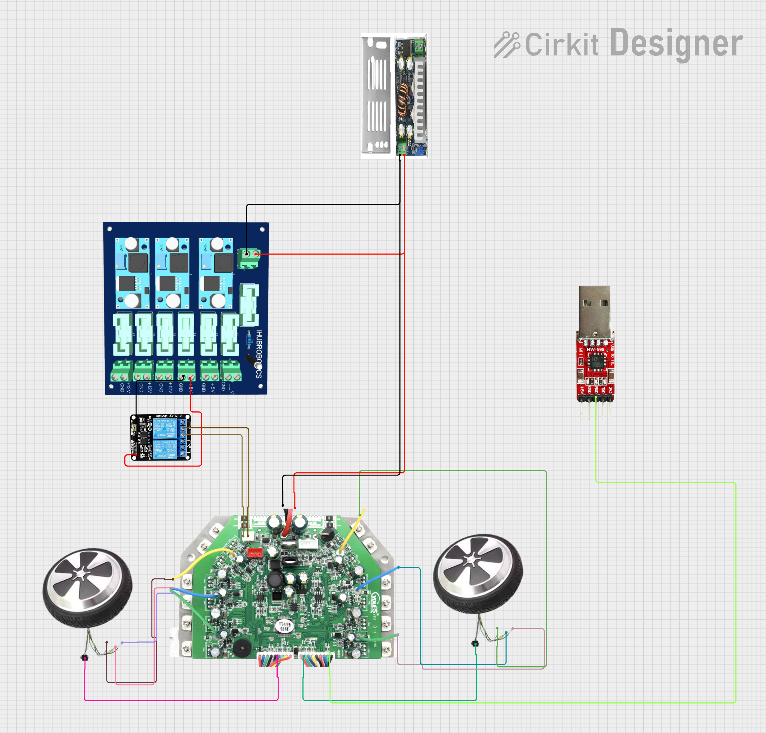
Circuit Documentation
Summary
This document provides a detailed overview of a circuit design that includes various components such as a DC-DC converter, hub motors, a USB to TTL converter, a hub driver, a power module, and a relay module. The document outlines the components used, their descriptions, wiring details, and any embedded code associated with the microcontrollers in the circuit.
Component List
DC-DC Converter
- Component Name: DC-DC Converter
- Pins: Out +ve, Out -ve, In +ve, In -ve
- Description: Converts DC voltage from one level to another.
- Purpose in Circuit: Provides the necessary voltage levels for other components.
Hub Motor
- Component Name: Hub Motor
- Pins: Hub green, Hub blue, Hub yellow, Hall sensor
- Description: Motor with integrated hall sensor for position feedback.
- Purpose in Circuit: Drives the mechanical load.
USB to TTL Converter
- Component Name: USB to TTL
- Pins: usb to system, HUB ttl
- Description: Converts USB signals to TTL level signals.
- Purpose in Circuit: Facilitates communication between the USB interface and the hub driver.
Hub Driver (24V to 55V Input)
- Component Name: HUB DRIVER 24V to 55V Input
- Pins: Hub 1 yellow, Hub 1 blue, Hub 1 green, Hub 2 Yellow, Hub 2 blue, Hub 2 Green, Hall Sensor 1, Hall Sensor 2, TTL, In +ve, In -ve, Hub On switch 2, Hub On switch 1
- Description: Drives the hub motors and processes hall sensor feedback.
- Purpose in Circuit: Controls the hub motors and interfaces with the USB to TTL converter.
Power Module (6 Channel)
- Component Name: Power Module 6 Channel
- Pins: In +ve, In -ve, 5V +ve, 12V +ve, 5V Gnd, 12V Gnd
- Description: Distributes power to various components.
- Purpose in Circuit: Provides regulated power supply to the circuit components.
5V 2-Relay JD-VCC
- Component Name: 5V 2-Relay JD-VCC
- Pins: JD-VCC, VCC, GND, IN1, IN2, NO, COM, NC
- Description: Relay module for switching applications.
- Purpose in Circuit: Controls the switching of the hub driver.
Wiring Details
DC-DC Converter
Out +ve is connected to:
- Power Module 6 Channel: In +ve
- HUB DRIVER 24V to 55V Input: In +ve
Out -ve is connected to:
- Power Module 6 Channel: In -ve
- HUB DRIVER 24V to 55V Input: In -ve
Hub Motor (Instance 1)
Hub green is connected to:
- HUB DRIVER 24V to 55V Input: Hub 1 green
Hub blue is connected to:
- HUB DRIVER 24V to 55V Input: Hub 1 blue
Hub yellow is connected to:
- HUB DRIVER 24V to 55V Input: Hub 1 yellow
Hall sensor is connected to:
- HUB DRIVER 24V to 55V Input: Hall Sensor 1
Hub Motor (Instance 2)
Hub green is connected to:
- HUB DRIVER 24V to 55V Input: Hub 2 Green
Hub blue is connected to:
- HUB DRIVER 24V to 55V Input: Hub 2 blue
Hub yellow is connected to:
- HUB DRIVER 24V to 55V Input: Hub 2 Yellow
Hall sensor is connected to:
- HUB DRIVER 24V to 55V Input: Hall Sensor 2
USB to TTL Converter
- HUB ttl is connected to:
- HUB DRIVER 24V to 55V Input: TTL
Power Module (6 Channel)
5V +ve is connected to:
- 5V 2-Relay JD-VCC: VCC
5V Gnd is connected to:
- 5V 2-Relay JD-VCC: GND
5V 2-Relay JD-VCC
COM is connected to:
- HUB DRIVER 24V to 55V Input: Hub On switch 2
NO is connected to:
- HUB DRIVER 24V to 55V Input: Hub On switch 1
Code
There is no embedded code provided for the microcontrollers in this circuit.
This document provides a comprehensive overview of the circuit design, including the components used, their descriptions, wiring details, and any associated code. This should serve as a useful reference for understanding and troubleshooting the circuit.