
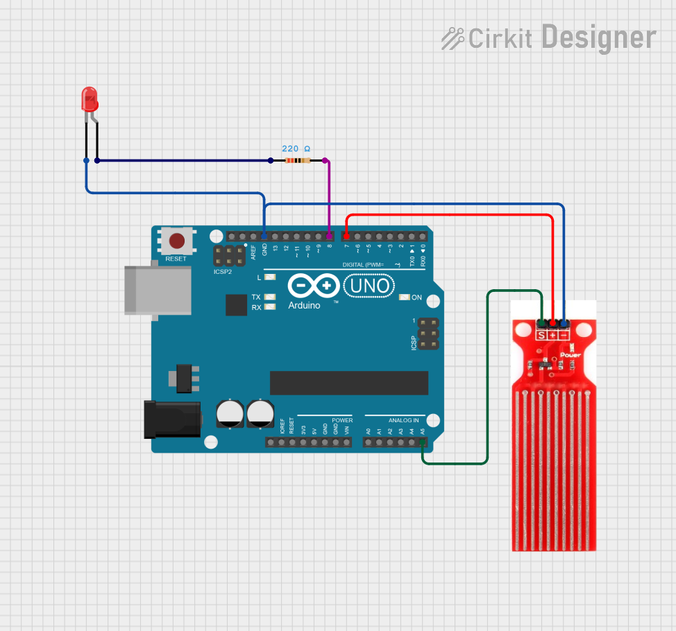
Circuit Documentation
Summary
This circuit is designed to monitor water levels using a water sensor and an Arduino UNO. When the water level falls below a predefined threshold, an LED will blink to indicate the low water level. The circuit includes a water sensor, an LED, a resistor, and an Arduino UNO microcontroller.
Component List
LED: Two Pin (red)
- Description: A red LED with two pins: cathode and anode.
- Pins: cathode, anode
Arduino UNO
- Description: A microcontroller board based on the ATmega328P.
- Pins: UNUSED, IOREF, Reset, 3.3V, 5V, GND, Vin, A0, A1, A2, A3, A4, A5, SCL, SDA, AREF, D13, D12, D11, D10, D9, D8, D7, D6, D5, D4, D3, D2, D1, D0
Water Sensor
- Description: A sensor to detect water levels.
- Pins: Signal, VCC, GND
Resistor
- Description: A resistor with a resistance of 220 Ohms.
- Pins: pin1, pin2
- Properties:
- Resistance: 220 Ohms
Wiring Details
LED: Two Pin (red)
- cathode is connected to:
- GND of the Water Sensor
- GND of the Arduino UNO
- anode is connected to:
- pin1 of the Resistor
Arduino UNO
- GND is connected to:
- GND of the Water Sensor
- cathode of the LED
- A5 is connected to:
- Signal of the Water Sensor
- D8 is connected to:
- pin2 of the Resistor
- D7 is connected to:
- VCC of the Water Sensor
Water Sensor
- GND is connected to:
- GND of the Arduino UNO
- cathode of the LED
- Signal is connected to:
- A5 of the Arduino UNO
- VCC is connected to:
- D7 of the Arduino UNO
Resistor
- pin1 is connected to:
- anode of the LED
- pin2 is connected to:
- D8 of the Arduino UNO
Code Documentation
#define POWER_PIN  7
#define METER_PIN  8
#define SIGNAL_PIN A5
#define LED_DELAY 250
#define WATER_LEVEL_MIN 30
int value = 0; // variable to store the sensor value

void setup() {
  Serial.begin(9600);
  pinMode(POWER_PIN, OUTPUT);   // configure D7 pin as an OUTPUT
  pinMode(METER_PIN, OUTPUT);
  digitalWrite(POWER_PIN, LOW); // turn the sensor OFF
}

void loop() {
  digitalWrite(POWER_PIN, HIGH);  // turn the sensor ON
  delay(10);                      // wait 10 milliseconds
  value = analogRead(SIGNAL_PIN); // read the analog value from sensor
  digitalWrite(POWER_PIN, LOW);   // turn the sensor OFF

  Serial.print("Sensor value: ");
  Serial.println(value);

  if (value < WATER_LEVEL_MIN)
  {
    digitalWrite(METER_PIN, HIGH);
    delay(LED_DELAY);
    digitalWrite(METER_PIN, LOW);
    delay(LED_DELAY);
  }
  else {
    digitalWrite(METER_PIN, LOW);
  }

  delay(1000);
}
Code Explanation
- POWER_PIN (D7): Controls the power to the water sensor.
- METER_PIN (D8): Controls the LED.
- SIGNAL_PIN (A5): Reads the analog signal from the water sensor.
- LED_DELAY: Delay time for LED blinking.
- WATER_LEVEL_MIN: Minimum water level threshold.
Setup Function:
- Initializes serial communication at 9600 baud.
- Configures D7 as an output to control the water sensor.
- Configures D8 as an output to control the LED.
- Turns off the water sensor initially.
Loop Function:
- Turns on the water sensor.
- Waits for 10 milliseconds to stabilize the sensor.
- Reads the analog value from the water sensor.
- Turns off the water sensor.
- Prints the sensor value to the serial monitor.
- If the sensor value is below the minimum water level, the LED blinks.
- If the sensor value is above the minimum water level, the LED remains off.
- Waits for 1 second before repeating the loop.