Cirkit Designer
Your all-in-one circuit design IDE
Home /
Project Documentation
Arduino and Stepper Motor Controlled Robotic Arm with Closed Loop Feedback
Circuit Documentation
Summary
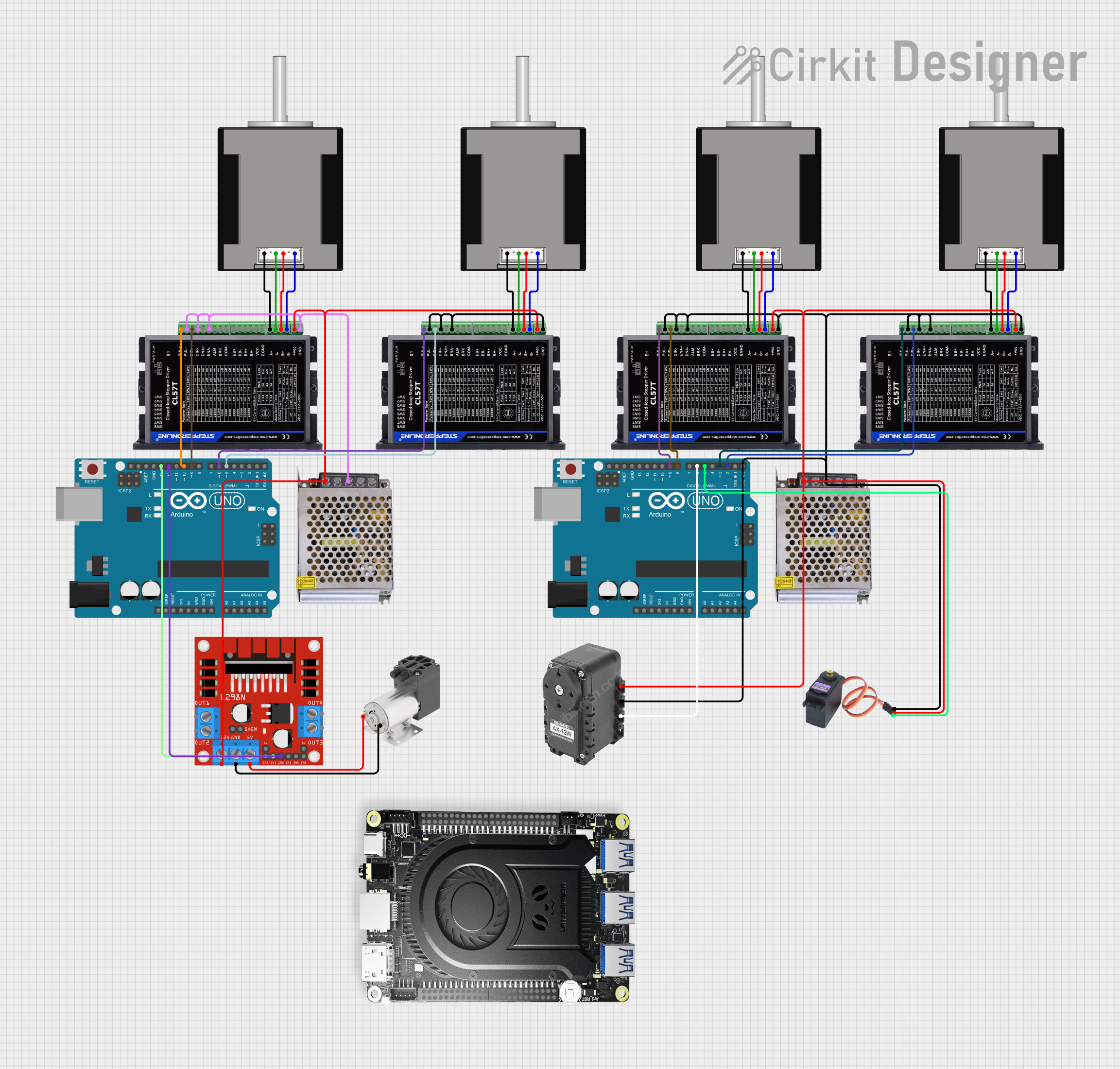
This document provides a detailed overview of a circuit that includes various components such as stepper motors, stepper drivers, power supplies, an Arduino UNO, a DC motor driver, a mini vacuum pump, and a Dynamixel motor. The circuit is designed to control multiple motors and a vacuum pump using an Arduino UNO microcontroller. The document includes a component list, wiring details, and documented code for the microcontrollers.
Component List
Nema 17 42-STH48
- Description: Stepper motor
- Pins: A2 (black), A1 (Green), B2 (Red), B1 (Blue)
Stepperonline CL57T Closed Loop Stepper Driver
- Description: Closed loop stepper driver
- Pins: PUL+, PUL-, DIR+, DIR-, ENA+, ENA-, ALM, BRK, COM-, EB+, EB-, EA+, EA-, VCC, A+, A-, B+, B-, +VDC, GND, EGND
POWER SUPPLY 12V 5AMP
- Description: Power supply
- Pins: 220V Positive Pole (AC), 220V Negative Pole (AC), GND, GND (DC), 12V-24V Output (DC)
Arduino UNO
- Description: Microcontroller
- Pins: UNUSED, IOREF, Reset, 3.3V, 5V, GND, Vin, A0, A1, A2, A3, A4, A5, SCL, SDA, AREF, D13, D12, D11, D10, D9, D8, D7, D6, D5, D4, D3, D2, D1, D0
Dynamixel Motor
- Description: Motor
- Pins: GND, Vdc, Data
L298N DC Motor Driver
- Description: DC motor driver
- Pins: OUT1, OUT2, 12V, GND, 5V, OUT3, OUT4, 5V-ENA-JMP-I, 5V-ENA-JMP-O, +5V-J1, +5V-J2, ENA, IN1, IN2, IN3, IN4, ENB
Mini Vacuum Pump
- Description: Vacuum pump
- Pins: +, -
MG996R
- Description: Servo motor
- Pins: GND, VCC, SIG
Lattepanda 3 Delta
- Description: Single-board computer
- Pins: GND, RST, SW, NC, S4, S3, S0, SPR+, SPR-, SPL+, 3.3V, SPL-, SCL, SDA, 1.8V, SGND, RI, DTR, CTS, TXD, RTS, RXD, DCD, DSR, D-, DC_IN, D+, 5V, RTC, MOSI, CLK, WP, HOLD, MISO, VCC, CS#, SCK, RESET, D7, DO-RXD1, A8-D8, D1-TXD1, A9-D9
, D2-SDA, A10-D10, D3-SCL, D11, D4-A6, A11-D12, D5, D13LED-D13, D6~A7, A3-D21, D18-A0, A4-D22, D19-A1, A5-D23, D20-A2
Wiring Details
Nema 17 42-STH48
- A2 (black) connected to Stepperonline CL57T Closed Loop Stepper Driver A+
- A1 (Green) connected to Stepperonline CL57T Closed Loop Stepper Driver A-
- B2 (Red) connected to Stepperonline CL57T Closed Loop Stepper Driver B+
- B1 (Blue) connected to Stepperonline CL57T Closed Loop Stepper Driver B-
Stepperonline CL57T Closed Loop Stepper Driver
- PUL+ connected to Arduino UNO D10
- DIR+ connected to Arduino UNO D9
- PUL- connected to POWER SUPPLY 12V 5AMP GND
- DIR- connected to POWER SUPPLY 12V 5AMP GND
- ENA- connected to POWER SUPPLY 12V 5AMP GND
- A+ connected to Nema 17 42-STH48 A2 (black)
- A- connected to Nema 17 42-STH48 A1 (Green)
- B+ connected to Nema 17 42-STH48 B2 (Red)
- B- connected to Nema 17 42-STH48 B1 (Blue)
- +VDC connected to POWER SUPPLY 12V 5AMP 12V-24V Output (DC)
- GND connected to POWER SUPPLY 12V 5AMP GND
POWER SUPPLY 12V 5AMP
- GND connected to Stepperonline CL57T Closed Loop Stepper Driver PUL-
- GND connected to Stepperonline CL57T Closed Loop Stepper Driver DIR-
- GND connected to Stepperonline CL57T Closed Loop Stepper Driver ENA-
- 12V-24V Output (DC) connected to Stepperonline CL57T Closed Loop Stepper Driver +VDC
Arduino UNO
- D13 connected to L298N DC Motor Driver IN1
- D12 connected to L298N DC Motor Driver IN2
- D10 connected to Stepperonline CL57T Closed Loop Stepper Driver PUL+
- D9 connected to Stepperonline CL57T Closed Loop Stepper Driver DIR+
- D6 connected to Dynamixel Motor Data
- D5 connected to MG996R SIG
- D3 connected to Stepperonline CL57T Closed Loop Stepper Driver PUL+
- D2 connected to Stepperonline CL57T Closed Loop Stepper Driver DIR+
Dynamixel Motor
- GND connected to POWER SUPPLY 12V 5AMP GND
- Vdc connected to POWER SUPPLY 12V 5AMP 12V-24V Output (DC)
- Data connected to Arduino UNO D6
L298N DC Motor Driver
- IN1 connected to Arduino UNO D13
- IN2 connected to Arduino UNO D12
- 12V connected to POWER SUPPLY 12V 5AMP 12V-24V Output (DC)
- GND connected to POWER SUPPLY 12V 5AMP GND
- 5V connected to Mini Vacuum Pump +
- GND connected to Mini Vacuum Pump -
Mini Vacuum Pump
- + connected to L298N DC Motor Driver 5V
- - connected to L298N DC Motor Driver GND
MG996R
- GND connected to POWER SUPPLY 12V 5AMP GND
- VCC connected to POWER SUPPLY 12V 5AMP 12V-24V Output (DC)
- SIG connected to Arduino UNO D5
Documented Code
Arduino UNO (Instance 1)
File Name: sketch.ino
void setup() {
  // put your setup code here, to run once:

}

void loop() {
  // put your main code here, to run repeatedly:

}
File Name: documentation.txt
Arduino UNO (Instance 2)
File Name: sketch.ino
void setup() {
  // put your setup code here, to run once:

}

void loop() {
  // put your main code here, to run repeatedly:

}
File Name: documentation.txt
This concludes the documentation for the circuit. If there are any questions or further clarifications needed, please feel free to reach out.