
Circuit Documentation
Summary
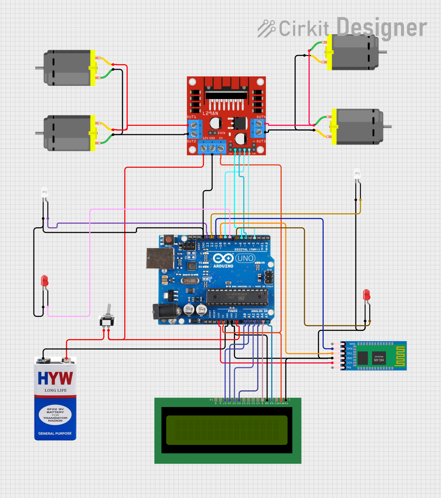
This project is an Arduino-based Bluetooth-controlled car. The car is equipped with four DC motors controlled by an L298N motor driver. It also features an HC-05 Bluetooth module for receiving commands, an LCD display for status messages, and several LEDs for visual indicators. The car's movement is controlled via Bluetooth commands received from a paired device.
Component List
Arduino Uno R3
- Description: Microcontroller board based on the ATmega328P.
- Pins: D8, D9, D10, D11, D12, D13, GND, AREF, SDA, SCL, D0/RX, D1/Tx, D2, D3, D4, D5, 6, D7, A5/SCL, A4/SDA, A3, A2, A1, A0, Vin, 5V, 3.3V, RESET, IOREF, NONE, USB Jack, Power Jack.
LCD 16x2 (Wokwi Compatible)
- Description: 16x2 character LCD display.
- Pins: VSS, VDD, V0, RS, RW, E, D0, D1, D2, D3, D4, D5, D6, D7, A, K.
HC-05 Bluetooth Module
- Description: Bluetooth module for wireless communication.
- Pins: Key, VCC, TXD, RXD, State, GND.
DC Motor
- Description: Standard DC motor.
- Pins: pin 1, pin 2.
9V Battery
- Description: Power source for the circuit.
- Pins: +, -.
Toggle Switch SPST
- Description: Single-pole single-throw toggle switch.
- Pins: L1, COM.
L298N DC Motor Driver
- Description: Dual H-Bridge motor driver.
- Pins: OUT1, OUT2, 12V, GND, 5V, OUT3, OUT4, 5V-ENA-JMP-I, 5V-ENA-JMP-O, +5V-J1, +5V-J2, ENA, IN1, IN2, IN3, IN4, ENB.
LED: Two Pin (Red)
- Description: Red LED.
- Pins: cathode, anode.
LED: Two Pin (White)
- Description: White LED.
- Pins: cathode, anode.
Wiring Details
Arduino Uno R3
- D8: Connected to the anode of the red LED.
- D9: Connected to IN3 of the L298N motor driver.
- D10: Connected to TXD of the HC-05 Bluetooth module.
- D11: Connected to RXD of the HC-05 Bluetooth module.
- D12: Connected to the anode of the white LED.
- D13: Connected to the anode of another white LED.
- GND: Connected to the cathode of the red LED, cathode of the white LED, GND of the L298N motor driver, GND of the HC-05 Bluetooth module, VSS and RW of the LCD, and the negative terminal of the 9V battery.
- D3: Connected to IN4 of the L298N motor driver.
- D5: Connected to IN2 of the L298N motor driver.
- 6: Connected to IN1 of the L298N motor driver.
- D7: Connected to the anode of another red LED.
- A5/SCL: Connected to RS of the LCD.
- A4/SDA: Connected to E of the LCD.
- A3: Connected to D4 of the LCD.
- A2: Connected to D5 of the LCD.
- A1: Connected to D6 of the LCD.
- A0: Connected to D7 of the LCD.
- Vin: Connected to 12V of the L298N motor driver and COM of the toggle switch.
- 5V: Connected to 5V of the L298N motor driver and VDD of the LCD.
- 3.3V: Connected to VCC of the HC-05 Bluetooth module.
LCD 16x2 (Wokwi Compatible)
- VSS: Connected to GND of the Arduino.
- VDD: Connected to 5V of the Arduino.
- RS: Connected to A5/SCL of the Arduino.
- RW: Connected to GND of the Arduino.
- E: Connected to A4/SDA of the Arduino.
- D4: Connected to A3 of the Arduino.
- D5: Connected to A2 of the Arduino.
- D6: Connected to A1 of the Arduino.
- D7: Connected to A0 of the Arduino.
HC-05 Bluetooth Module
- VCC: Connected to 3.3V of the Arduino.
- TXD: Connected to D10 of the Arduino.
- RXD: Connected to D11 of the Arduino.
- GND: Connected to GND of the Arduino.
L298N DC Motor Driver
- IN3: Connected to D9 of the Arduino.
- IN4: Connected to D3 of the Arduino.
- IN2: Connected to D5 of the Arduino.
- IN1: Connected to 6 of the Arduino.
- GND: Connected to GND of the Arduino.
- 12V: Connected to Vin of the Arduino and COM of the toggle switch.
- 5V: Connected to 5V of the Arduino.
- OUT1: Connected to pin 2 of two DC motors.
- OUT2: Connected to pin 1 of two DC motors.
- OUT3: Connected to pin 2 of two other DC motors.
- OUT4: Connected to pin 1 of two other DC motors.
DC Motor
- pin 1: Connected to OUT2 or OUT4 of the L298N motor driver.
- pin 2: Connected to OUT1 or OUT3 of the L298N motor driver.
9V Battery
- +: Connected to GND of the Arduino.
- -: Connected to L1 of the toggle switch.
Toggle Switch SPST
- L1: Connected to the negative terminal of the 9V battery.
- COM: Connected to Vin of the Arduino and 12V of the L298N motor driver.
LED: Two Pin (Red)
- anode: Connected to D8 or D7 of the Arduino.
- cathode: Connected to GND of the Arduino.
LED: Two Pin (White)
- anode: Connected to D12 or D13 of the Arduino.
- cathode: Connected to GND of the Arduino.
Code Documentation
/*
 * Arduino Based Bluetooth Car
 * This code controls a car using an Arduino Uno and an HC-05 Bluetooth module.
 * The car has four DC motors controlled by an L298N motor driver.
 * The car's movement is controlled via Bluetooth commands received from a
 * paired device. The car also has an LCD display to show status messages.
 */

#include <LiquidCrystal.h>

// Pin definitions
const int motor1Pin1 = 6;
const int motor1Pin2 = 5;
const int motor2Pin1 = 9;
const int motor2Pin2 = 3;
const int ledRedPin = 8;
const int ledWhitePin1 = 12;
const int ledWhitePin2 = 13;
const int rxPin = 11;
const int txPin = 10;

// LCD pin definitions
const int rs = A5;
const int en = A4;
const int d4 = A3;
const int d5 = A2;
const int d6 = A1;
const int d7 = A0;

LiquidCrystal lcd(rs, en, d4, d5, d6, d7);

void setup() {
  // Initialize motor pins
  pinMode(motor1Pin1, OUTPUT);
  pinMode(motor1Pin2, OUTPUT);
  pinMode(motor2Pin1, OUTPUT);
  pinMode(motor2Pin2, OUTPUT);

  // Initialize LED pins
  pinMode(ledRedPin, OUTPUT);
  pinMode(ledWhitePin1, OUTPUT);
  pinMode(ledWhitePin2, OUTPUT);

  // Initialize serial communication
  Serial.begin(9600);

  // Initialize LCD
  lcd.begin(16, 2);
  lcd.print("Bluetooth Car");
}

void loop() {
  if (Serial.available() > 0) {
    char command = Serial.read();
    executeCommand(command);
  }
}

void executeCommand(char command) {
  switch (command) {
    case 'F':
      moveForward();
      break;
    case 'B':
      moveBackward();
      break;
    case 'L':
      turnLeft();
      break;
    case