Cirkit Designer
Your all-in-one circuit design IDE
Home /
Project Documentation
ESP32C3-Based Thermal Imaging System with TFT Display and SD Card Storage
Circuit Documentation
Summary
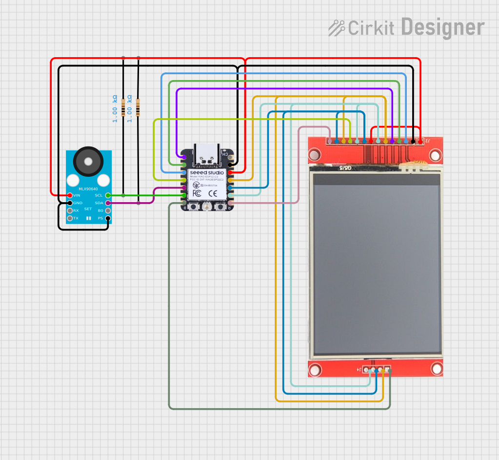
This circuit integrates a Seeed Studio XIAO ESP32C3 microcontroller with a GY-MCU90640 thermal camera, an ili9341 TFT display, and an SPI SD card module. The microcontroller reads thermal data from the GY-MCU90640 and displays it on the ili9341 TFT display. Additionally, the microcontroller can store data on the SPI SD card. The circuit is powered by the 3.3V and GND pins of the XIAO ESP32C3.
Component List
XIAO ESP32C3
- Description: A compact microcontroller based on the ESP32-C3 chip.
- Pins: GPIO2/A0/D0, GPIO3/A1/D1, GPIO4/A2/D2, GPIO5/A3/D3, GPIO6/SDA/D4, GPIO7/SCL/D5, GPIO21/Tx/D6, 5V, GND, 3V3, GPIO10/MOSI/D10, GPIO9/MISO/D9, GPIO8/SCK/D8, GPIO20/Rx/D7
GY-MCU90640
- Description: A thermal camera module.
- Pins: Pin 1, Pin 2, Pin 3, Pin 4, Pin 5, Pin 6, Pin 7, Pin 8
SPI SD Card
- Description: An SPI-based SD card module.
- Pins: SD-CS, SD-MOSI, SD-MISO, SD-SCK
ili9341 TFT Display
- Description: A TFT display module with touch functionality.
- Pins: VCC, GND, CS, RESET, DC/RS, SDI, SCK, LED, SDO, T_CLK, T_CS, T_DIN, T_DO, T_IRQ
Resistor (1k Ohms)
- Description: A resistor with a resistance of 1000 Ohms.
- Pins: pin1, pin2
Wiring Details
XIAO ESP32C3
- GPIO2/A0/D0: Connected to ili9341 TFT display DC/RS
- GPIO3/A1/D1: Connected to ili9341 TFT display RESET
- GPIO4/A2/D2: Connected to ili9341 TFT display CS
- GPIO5/A3/D3: Connected to ili9341 TFT display T_CS
- GPIO6/SDA/D4: Connected to GY-MCU90640 Pin 7
- GPIO7/SCL/D5: Connected to GY-MCU90640 Pin 8
- GPIO21/Tx/D6: Connected to SPI SD card SD-CS
- GND: Connected to GY-MCU90640 Pin 2, GY-MCU90640 Pin 5, ili9341 TFT display GND
- 3V3: Connected to GY-MCU90640 Pin 1, ili9341 TFT display VCC, ili9341 TFT display LED
- GPIO10/MOSI/D10: Connected to SPI SD card SD-MOSI, ili9341 TFT display T_DIN, ili9341 TFT display SDI
- GPIO9/MISO/D9: Connected to SPI SD card SD-MISO, ili9341 TFT display T_DO, ili9341 TFT display SDO
- GPIO8/SCK/D8: Connected to SPI SD card SD-SCK, ili9341 TFT display SCK, ili9341 TFT display T_CLK
- GPIO20/Rx/D7: Connected to ili9341 TFT display T_IRQ
GY-MCU90640
- Pin 1: Connected to XIAO ESP32C3 3V3
- Pin 2: Connected to XIAO ESP32C3 GND
- Pin 5: Connected to XIAO ESP32C3 GND
- Pin 7: Connected to XIAO ESP32C3 GPIO6/SDA/D4
- Pin 8: Connected to XIAO ESP32C3 GPIO7/SCL/D5
SPI SD Card
- SD-CS: Connected to XIAO ESP32C3 GPIO21/Tx/D6
- SD-MOSI: Connected to XIAO ESP32C3 GPIO10/MOSI/D10
- SD-MISO: Connected to XIAO ESP32C3 GPIO9/MISO/D9
- SD-SCK: Connected to XIAO ESP32C3 GPIO8/SCK/D8
ili9341 TFT Display
- VCC: Connected to XIAO ESP32C3 3V3
- GND: Connected to XIAO ESP32C3 GND
- CS: Connected to XIAO ESP32C3 GPIO4/A2/D2
- RESET: Connected to XIAO ESP32C3 GPIO3/A1/D1
- DC/RS: Connected to XIAO ESP32C3 GPIO2/A0/D0
- SDI: Connected to XIAO ESP32C3 GPIO10/MOSI/D10
- SCK: Connected to XIAO ESP32C3 GPIO8/SCK/D8
- LED: Connected to XIAO ESP32C3 3V3
- SDO: Connected to XIAO ESP32C3 GPIO9/MISO/D9
- T_CLK: Connected to XIAO ESP32C3 GPIO8/SCK/D8
- T_CS: Connected to XIAO ESP32C3 GPIO5/A3/D3
- T_DIN: Connected to XIAO ESP32C3 GPIO10/MOSI/D10
- T_DO: Connected to XIAO ESP32C3 GPIO9/MISO/D9
- T_IRQ: Connected to XIAO ESP32C3 GPIO20/Rx/D7
Documented Code
#include <Adafruit_MLX90640.h>
#include <Adafruit_GFX.h>    // Core graphics library
#include <Adafruit_ST7789.h> // Hardware-specific library for ST7789
#include <SPI.h>

#if defined(ARDUINO_UNOR4_WIFI) || defined(ARDUINO_UNOR4_MINIMA)
// For the breakout board, you can use any 2 or 3 pins.
// These pins will also work for the 1.8" TFT shield.
/* SPI pin definition for Arduino UNO R3 and R4
  | ST7789 | PIN  |  R3  |   R4   |     Description      |
  |--------|------|------|--------|----------------------|
  | SCL    |  D13 | SCK  | RSPCKA | Serial clock         |
  | SDA    | ~D11 | COPI | COPIA  | Serial data input    |
  | RES    | ~D9  | PB1  | P303   | Reset signal         |
  | DC     |  D8  | PB0  | P304   | Display data/command |
*/
#define TFT_CS        10
#define TFT_RST        9 // Or set to -1 and connect to Arduino RESET pin
#define TFT_DC         8
#define SPI_MODE      SPI_MODE3 // SPI_MODE2 or SPI_MODE3

#elif defined(ARDUINO_XIAO_ESP32S3)
// Seeed Studio XIAO ESP32-S3
#define TFT_MOSI      D10
#define TFT_MISO      D9
#define TFT_SCLK      D8
#define TFT_CS        D2    // (-1)  // dummy
#define TFT_RST       D1    // Or set to -1 and connect to Arduino RESET pin
#define TFT_DC        D0
#define SPI_MODE      SPI_MODE3 // SPI_MODE3

#else
#warning "must specify board type"
#endif

Adafruit_ST7789 tft = Adafruit_ST7789(TFT_CS, TFT_DC, TFT_RST);

#if 0
// 1.3 inch ... TFT_RST must be D9
#define DEVICE_WIDTH    240
#define DEVICE_HEIGHT   240
#define DEVICE_ORIGIN   2
#define PIXEL_SIZE      7
#define INVERT_DISPLAY  true
#else
// 2.4 inch ... "RESET" on breakout board can be connected to "RESET" or +3.3V on UNO R4 instead of D9.
#define DEVICE_WIDTH    240
#define DEVICE_HEIGHT   320
#define DEVICE_ORIGIN   1
#define PIXEL_SIZE      7
#define INVERT_DISPLAY  false
#endif

// Font size for setTextSize(2)
#define FONT_WIDTH    12 // [px] (Device coordinate system)
#define FONT_HEIGHT   16 // [px] (Device coordinate system)

#define ClearScreen() tft.fillScreen(ST77XX_BLACK)

Adafruit_MLX90640 mlx;
float frame[32*24]; // buffer for full frame of temperatures

//low range of the sensor (this will be blue on the screen)
#define MINTEMP 20

//high range of the sensor (this will be red on the screen)
#define MAXTEMP 35

//the colors we will be using