
Configurable Battery-Powered RF Signal Transmitter with DIP Switch Settings
View and Edit Project In Cirkit Designer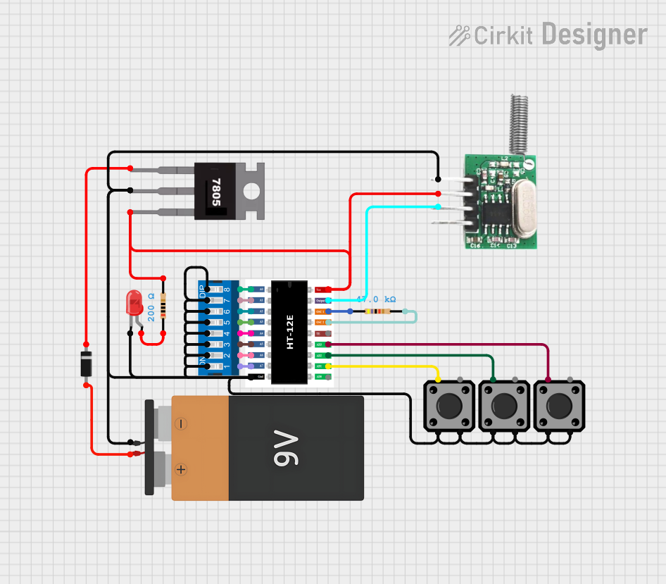
Circuit Documentation
Summary
This circuit appears to be designed for encoding and transmitting data wirelessly using an RF 433 MHz transmitter. The encoder is interfaced with a DIP switch to set the input data, and the output is transmitted via the RF module. The circuit includes a voltage regulation section using a 7805 regulator to ensure a stable 5V supply for the encoder and RF transmitter. Additionally, there are tactile switches connected to the encoder for manual data input, and an LED with a current-limiting resistor to indicate the status or for debugging purposes.
Component List
Encoder
- Component Name: Encoder, 2/12 Series, CMOS, 2.4 V to 12 V, DIP-18
- Description: An encoder chip used for encoding data inputs into a serial data output.
- Pins: A0-A7, GND, VCC, DO, OSC1, OSC2, TE, D3, D2, D1, D0
Battery
- Component Name: Battery 9V
- Description: Provides the power supply for the circuit.
Voltage Regulator
- Component Name: 7805
- Description: A voltage regulator that outputs a stable 5V from a higher voltage input.
- Pins: Vin, Gnd, Vout
Diode
- Component Name: Diode
- Description: Prevents reverse current flow, protecting the circuit components.
- Pins: cathode, anode
LED
- Component Name: LED: Two Pin (red)
- Description: Indicates the operational status or for debugging.
- Pins: cathode, anode
Tactile Switches
- Component Name: Tactile Switch Buttons - 12mm Square
- Description: Provides a manual interface for user input.
- Pins: 3, 1, 4, 2
Resistors
- Component Name: Resistor
- Description: Limits current or provides a voltage drop.
- Properties: Various resistances (47k Ohms, 200 Ohms)
DIP Switch
- Component Name: DIP Switch (8 Position)
- Description: Allows for setting the encoder inputs manually.
- Pins: 1-16
RF Transmitter
- Component Name: RF 433 MHz Transmitter
- Description: Transmits the encoded data wirelessly.
- Pins: -ve, Data, +ve
Wiring Details
Encoder
- A0-A7: Connected to DIP Switch (8 Position) pins 1-8 respectively.
- GND: Common ground with other components.
- VCC: Connected to the output of the 7805 voltage regulator through a 200 Ohm resistor.
- DO: Connected to the Data pin of the RF 433 MHz Transmitter.
- OSC1, OSC2: Connected to a 47k Ohm resistor.
- TE: Not connected.
- D3, D2, D1, D0: Connected to tactile switches.
Battery 9V
- VCC: Connected to the anode of the Diode.
- GND: Common ground with other components.
Voltage Regulator 7805
- Vin: Connected to the cathode of the Diode.
- Gnd: Common ground with other components.
- Vout: Connected to the VCC of the Encoder and the +ve of the RF 433 MHz Transmitter.
Diode
- anode: Connected to the VCC of the Battery 9V.
- cathode: Connected to the Vin of the 7805 voltage regulator.
LED
- anode: Connected to the VCC through a 200 Ohm resistor.
- cathode: Connected to the common ground.
Tactile Switches
- Each switch has one pin connected to the Encoder (D3, D2, D1, D0) and the other pins are not used or connected.
Resistors
- 47k Ohm: Connected between OSC1 and OSC2 of the Encoder.
- 200 Ohm: Connected between the Vout of the 7805 and VCC of the Encoder, and between the VCC and the anode of the LED.
DIP Switch (8 Position)
- Pins 1-8: Connected to A0-A7 of the Encoder.
- Other pins: Not used or connected.
RF 433 MHz Transmitter
- -ve: Common ground with other components.
- Data: Connected to the DO of the Encoder.
- +ve: Connected to the Vout of the 7805 voltage regulator.
Documented Code
There is no code provided for any microcontrollers in the circuit. If there is a microcontroller involved, its code would be necessary to fully understand the operation of the circuit, especially how it handles the inputs from the DIP switch and tactile switches, and how it controls the RF transmitter.