ESP32-Controlled RGB LED Indicator
Circuit Documentation
Summary
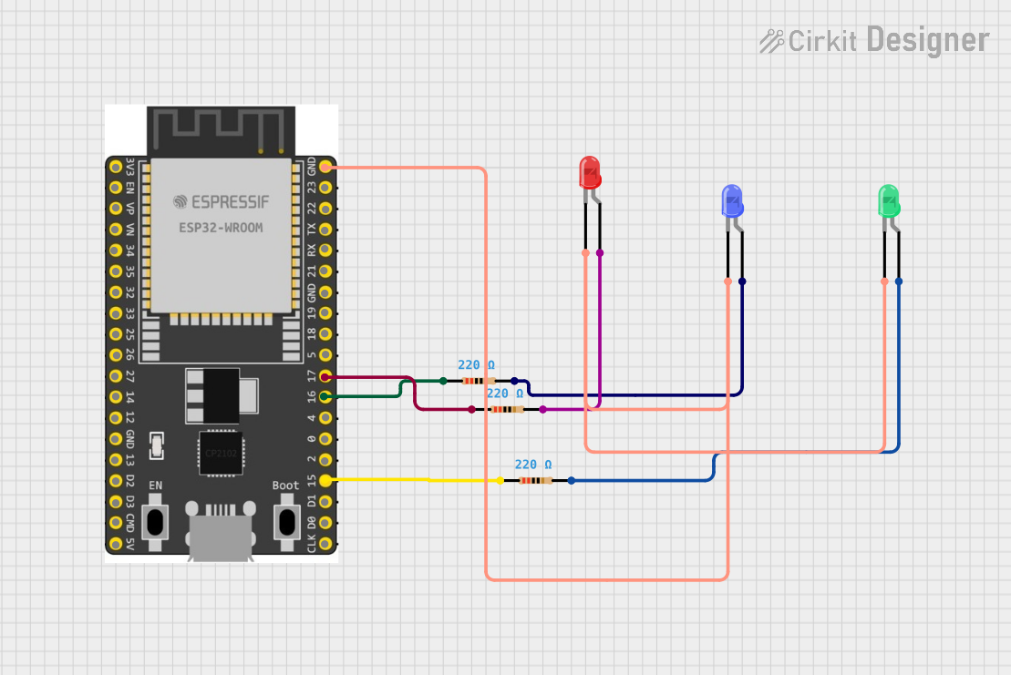
The circuit in question is designed around the ESP32 Wroom Dev Kit, which is a popular microcontroller with Wi-Fi and Bluetooth capabilities. The circuit includes three LEDs (red, green, and blue) each with a corresponding resistor to limit the current through the LEDs. The ESP32 is configured to control the LEDs via its GPIO pins. The ground pins of all LEDs are connected together and to the ground of the ESP32. Each LED is connected to a GPIO pin through a resistor. The absence of code suggests that the microcontroller's firmware has not been provided or is not required for this documentation.
Component List
ESP32 Wroom Dev Kit
- Description: A microcontroller development board with Wi-Fi and Bluetooth capabilities.
- Pins: 3V3, EN, VP, VN, GPIO 34, GPIO 35, GPIO 32, GPIO 33, GPIO 25, GPIO 26, GPIO 27, GPIO 14, GND, GPIO 13, SD2, SD3, CMD, V5, GPIO 23, GPIO 22, TXD, RXD, GPIO 21, GPIO 19, GPIO 18, GPIO 5, GPIO 17, GPIO 16, GPIO 4, GPIO 0, GPIO 2, GPIO 15, SD1, SD0, CLK
LED: Two Pin (red)
- Description: A red light-emitting diode.
- Pins: cathode, anode
LED: Two Pin (green)
- Description: A green light-emitting diode.
- Pins: cathode, anode
LED: Two Pin (blue)
- Description: A blue light-emitting diode.
- Pins: cathode, anode
Resistor (220 Ohms)
- Description: A resistor with a resistance of 220 Ohms.
- Pins: pin1, pin2
Wiring Details
ESP32 Wroom Dev Kit
- GND connected to:
- Red LED cathode
- Blue LED cathode
- Green LED cathode
- GPIO 17 connected to:
- Resistor (pin1) leading to the red LED
- GPIO 16 connected to:
- Resistor (pin1) leading to the blue LED
- GPIO 15 connected to:
- Resistor (pin1) leading to the green LED
LED: Two Pin (red)
- Cathode connected to ESP32 GND
- Anode connected to Resistor (pin2)
LED: Two Pin (green)
- Cathode connected to ESP32 GND
- Anode connected to Resistor (pin2)
LED: Two Pin (blue)
- Cathode connected to ESP32 GND
- Anode connected to Resistor (pin2)
Resistor (220 Ohms)
- Pin1 connected to ESP32 GPIO pin (17, 16, or 15 depending on the LED color)
- Pin2 connected to the corresponding LED anode
Documented Code
No code has been provided for the microcontroller. The expected behavior, based on the hardware configuration, would be to toggle the GPIO pins 15, 16, and 17 to turn on and off the respective LEDs. Without the code, the operation of the circuit cannot be fully described.