Arduino Nano Based GPS Tracker with GSM Reporting
Circuit Documentation
Summary
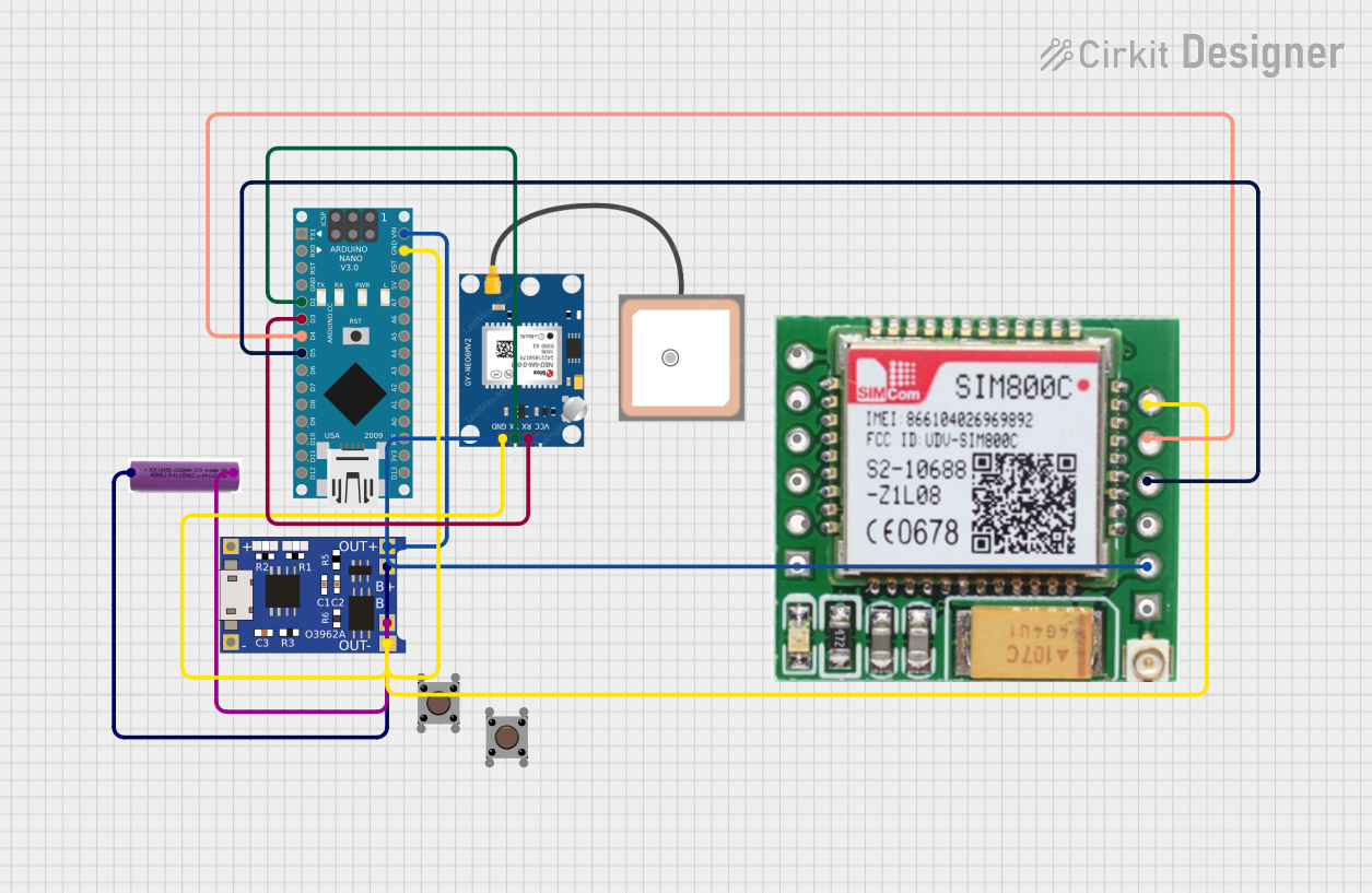
This circuit integrates an Arduino Nano with a GPS NEO 6M module and a SIM800c GSM module to read GPS data and send it via GSM. The circuit is powered by a 3.7V battery connected through a TP4056 charging module, ensuring a stable power supply for the components. The Arduino Nano serves as the central processing unit, interfacing with the GPS module for location data and the GSM module for cellular communication.
Component List
Arduino Nano
- Microcontroller board based on the ATmega328P
- It has a variety of digital and analog I/O pins and supports serial communication.
GPS NEO 6M
- A GPS module capable of providing geolocation information.
- It communicates with the Arduino Nano via serial connection.
SIM800c GSM Module
- A GSM/GPRS module that allows cellular network connectivity.
- It can send SMS, make calls, and transfer data over a mobile network.
TP4056
- A lithium battery charge management and protection module.
- It is used for charging the 3.7V battery and providing power to the circuit.
3.7V Battery
- A lithium-ion battery that supplies power to the circuit.
Pushbutton (x2)
- A simple switch mechanism for control or input.
Wiring Details
Arduino Nano
- D2: Connected to GPS NEO 6M TX
- D3: Connected to GPS NEO 6M RX
- D4: Connected to SIM800c GSM Module TXD
- D5: Connected to SIM800c GSM Module RXD
- VIN: Connected to TP4056 OUT+
- GND: Connected to TP4056 OUT-
GPS NEO 6M
- VCC: Connected to Arduino Nano VIN
- RX: Connected to Arduino Nano D3
- TX: Connected to Arduino Nano D2
- GND: Connected to Arduino Nano GND
SIM800c GSM Module
- VCC(3.7 - 4.2): Connected to Arduino Nano VIN
- TXD: Connected to Arduino Nano D4
- RXD: Connected to Arduino Nano D5
- GND: Connected to Arduino Nano GND
TP4056
- OUT+: Connected to Arduino Nano VIN, GPS NEO 6M VCC, and SIM800c GSM Module VCC
- OUT-: Connected to Arduino Nano GND, GPS NEO 6M GND, and SIM800c GSM Module GND
- B+: Connected to 3.7V battery +
- B-: Connected to 3.7V battery -
3.7V Battery
- +: Connected to TP4056 B+
- -: Connected to TP4056 B-
Pushbutton (x2)
- Not connected in the current circuit configuration.
Documented Code
/*
 * Arduino Nano GPS and GSM Module Interface
 *
 * This code reads GPS data from the NEO 6M module and sends it via the
 * SIM800c GSM module. The GPS module is connected to pins D2 (TX) and D3 (RX)
 * of the Arduino Nano. The GSM module is connected to pins D4 (TXD) and D5 (RXD).
 */

#include <SoftwareSerial.h>

// GPS module connections
#define GPS_TX_PIN 2
#define GPS_RX_PIN 3

// GSM module connections
#define GSM_TX_PIN 4
#define GSM_RX_PIN 5

SoftwareSerial gpsSerial(GPS_TX_PIN, GPS_RX_PIN); // RX, TX
SoftwareSerial gsmSerial(GSM_TX_PIN, GSM_RX_PIN); // RX, TX

void setup() {
  // Initialize serial communication
  Serial.begin(9600);
  gpsSerial.begin(9600);
  gsmSerial.begin(9600);

  // Wait for GSM module to initialize
  delay(1000);
  Serial.println("GSM Module Initialized");
}

void loop() {
  // Read data from GPS module
  if (gpsSerial.available()) {
    String gpsData = gpsSerial.readString();
    Serial.println("GPS Data: " + gpsData);

    // Send GPS data via GSM module
    gsmSerial.println(gpsData);
    Serial.println("Data sent via GSM");
  }

  // Small delay to avoid flooding
  delay(1000);
}
This code is designed to be uploaded to the Arduino Nano. It initializes two software serial ports for communication with the GPS and GSM modules, reads data from the GPS module, and sends it through the GSM module. The code includes a setup routine that initializes the serial ports and a loop that continuously reads and sends GPS data.