
Circuit Documentation
Summary of the Circuit
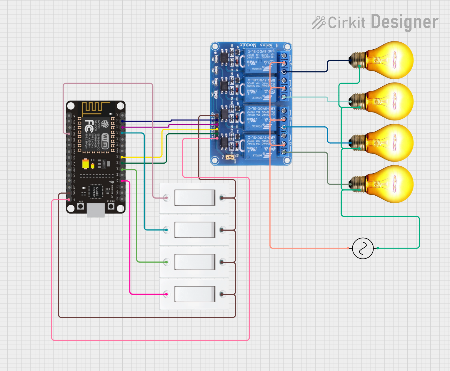
The circuit described by the provided inputs is a smart lighting control system using an ESP8266 NodeMCU microcontroller to operate multiple AC bulbs through a 4-channel relay module. The system is designed to control the bulbs via digital signals from the ESP8266 NodeMCU, which can be programmed to respond to various inputs, such as commands from a network or connected switches.
Component List
ESP8266 NodeMCU
- Description: A Wi-Fi capable microcontroller module based on the ESP8266 chip.
- Pins: D0, D1, D2, D3, D4, 3V3, GND, D5, D6, D7, D8, RX, TX, A0, RSV, SD3, SD2, SD1, CMD, SD0, CLK, EN, RST, VIN
AC Bulb
- Description: A standard AC-powered light bulb.
- Pins: P (Phase), N (Neutral)
Flush Switch
- Description: A push-button switch used to provide a user interface for controlling the circuit.
- Pins: GND, VCC
Relay 4 Channel 5V
- Description: A 4-channel relay module that allows for controlling high power devices with low power signals.
- Pins: GND, IN1, IN2, IN3, IN4, VCC, COM1, COM2, COM3, COM4, NO1, NO2, NO3, NO4, NC1, NC2, NC3, NC4
AC Supply
- Description: The main AC power source for the circuit.
- Pins: +ve (Live), -ve (Neutral)
Wiring Details
ESP8266 NodeMCU
- D1 connected to Relay IN1
- D2 connected to Relay IN2
- D3 connected to Flush Switch VCC (Instance 1)
- D5 connected to Relay IN3
- D6 connected to Relay IN4
- D7 connected to Flush Switch VCC (Instance 2)
- RX connected to Flush Switch VCC (Instance 3)
- SD3 connected to Flush Switch VCC (Instance 4)
- GND connected to common ground net
- VIN connected to Relay VCC
AC Bulb (4 Instances)
- P (Phase) of each bulb connected to corresponding NO (Normally Open) pin on Relay (NO1, NO2, NO3, NO4)
- N (Neutral) of all bulbs connected to AC Supply -ve
Flush Switch (4 Instances)
- VCC of each switch connected to different GPIO pins on ESP8266 NodeMCU (D3, D7, RX, SD3)
- GND of all switches connected to common ground net
Relay 4 Channel 5V
- IN1, IN2, IN3, IN4 connected to ESP8266 NodeMCU (D1, D2, D5, D6)
- VCC connected to ESP8266 NodeMCU VIN
- GND connected to common ground net
- COM1, COM2, COM3, COM4 connected to AC Supply +ve
- NO1, NO2, NO3, NO4 connected to P (Phase) of each AC Bulb
AC Supply
- +ve connected to COM pins on Relay
- -ve connected to N (Neutral) of all AC Bulbs
Documented Code
No code was provided for the microcontroller. The ESP8266 NodeMCU would typically be programmed to control the relay channels based on inputs from the flush switches or network commands. The code would include setup routines for configuring GPIO pins, routines for handling switch presses, and possibly network communication for remote operation.
Since no code is available, it is recommended to develop firmware that initializes the GPIO pins connected to the relay module and flush switches, sets up Wi-Fi connectivity, and implements control logic for the lighting system. The firmware should also include debouncing for the flush switches and safety features to handle unexpected behaviors.