
Arduino UNO and ESP32 CAM Controlled Ultrasonic Sensor with Servo Motors
View and Edit Project In Cirkit Designer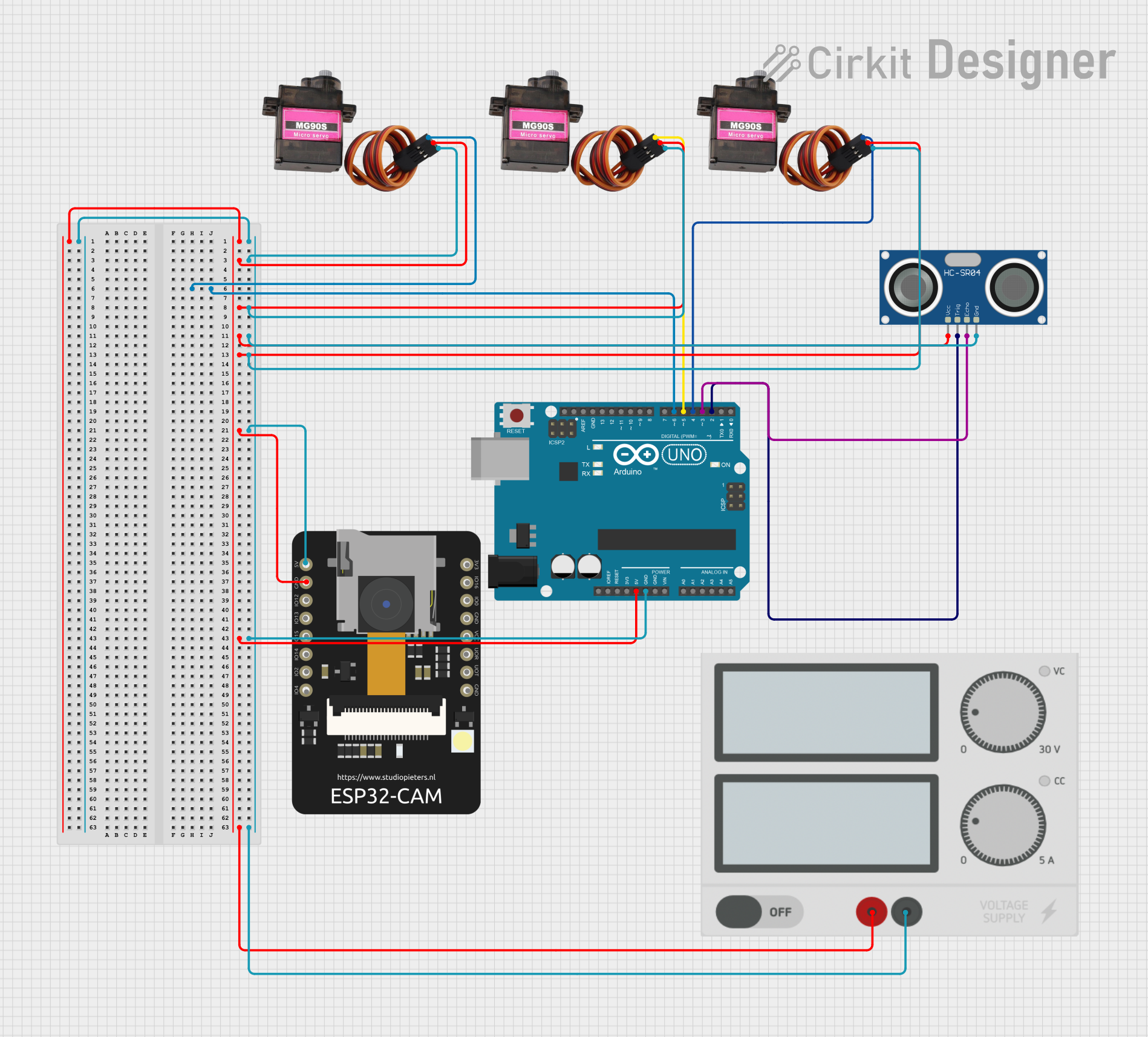
Circuit Documentation
Summary of the Circuit
This circuit is designed to interface an Arduino UNO with multiple peripherals including an HC-SR04 Ultrasonic Sensor and three MG90S servo motors. Additionally, an ESP32 CAM module is included in the circuit. The power supply is connected to provide the necessary voltage levels to the components. The Arduino UNO serves as the central microcontroller unit to control the servo motors based on the input from the ultrasonic sensor and potentially communicate with the ESP32 CAM module.
Component List
Arduino UNO
- Description: A microcontroller board based on the ATmega328P.
- Pins: UNUSED, IOREF, Reset, 3.3V, 5V, GND, Vin, A0-A5, SCL, SDA, AREF, D0-D13.
HC-SR04 Ultrasonic Sensor
- Description: An ultrasonic distance sensor.
- Pins: VCC, TRIG, ECHO, GND.
MG90S Servo Motor
- Description: A micro servo motor for precise angular movement.
- Pins: SIG, VCC, GND.
Power Supply
- Description: Provides power to the circuit.
- Pins: + (positive supply), - (ground).
ESP32 CAM
- Description: A small-sized ESP32-based board with camera support.
- Pins: 5V, GND, GPIO12, GPIO13, GPIO15, GPIO14, GPIO2, GPIO4, 3.3V, GPIO16, GPIO0, 3.3V / 5V / P_OUT, GPIO3 / RX, GPIO1 / TX.
Wiring Details
Arduino UNO
- 5V connected to VCC of all MG90S servo motors, HC-SR04 Ultrasonic Sensor, and GND of ESP32 CAM.
- GND connected to GND of all MG90S servo motors, HC-SR04 Ultrasonic Sensor, and 5V of ESP32 CAM.
- D6 connected to SIG of one MG90S servo motor.
- D5 connected to SIG of another MG90S servo motor.
- D4 connected to SIG of the third MG90S servo motor.
- D3 connected to ECHO of HC-SR04 Ultrasonic Sensor.
- D2 connected to TRIG of HC-SR04 Ultrasonic Sensor.
HC-SR04 Ultrasonic Sensor
- VCC connected to 5V of Arduino UNO.
- TRIG connected to D2 of Arduino UNO.
- ECHO connected to D3 of Arduino UNO.
- GND connected to GND of Arduino UNO.
MG90S Servo Motors
- SIG of each servo connected to D6, D5, and D4 of Arduino UNO respectively.
- VCC of all servos connected to 5V of Arduino UNO.
- GND of all servos connected to GND of Arduino UNO.
Power Supply
- + connected to 5V of Arduino UNO and VCC of all MG90S servo motors, HC-SR04 Ultrasonic Sensor.
- - connected to GND of Arduino UNO and GND of all MG90S servo motors, HC-SR04 Ultrasonic Sensor.
ESP32 CAM
- 5V connected to GND of Arduino UNO.
- GND connected to 5V of Arduino UNO.
Documented Code
Arduino UNO Code (sketch.ino)
void setup() {
  // put your setup code here, to run once:

}

void loop() {
  // put your main code here, to run repeatedly:

}
Note: The provided code for the Arduino UNO is a template with empty setup and loop functions. The actual implementation should be added to control the servo motors based on the ultrasonic sensor readings and handle communication with the ESP32 CAM module.