Cirkit Designer
Your all-in-one circuit design IDE
Home /
Project Documentation
9V Battery-Powered DC Motor with Toggle Switch Control
Circuit Documentation
Summary of the Circuit
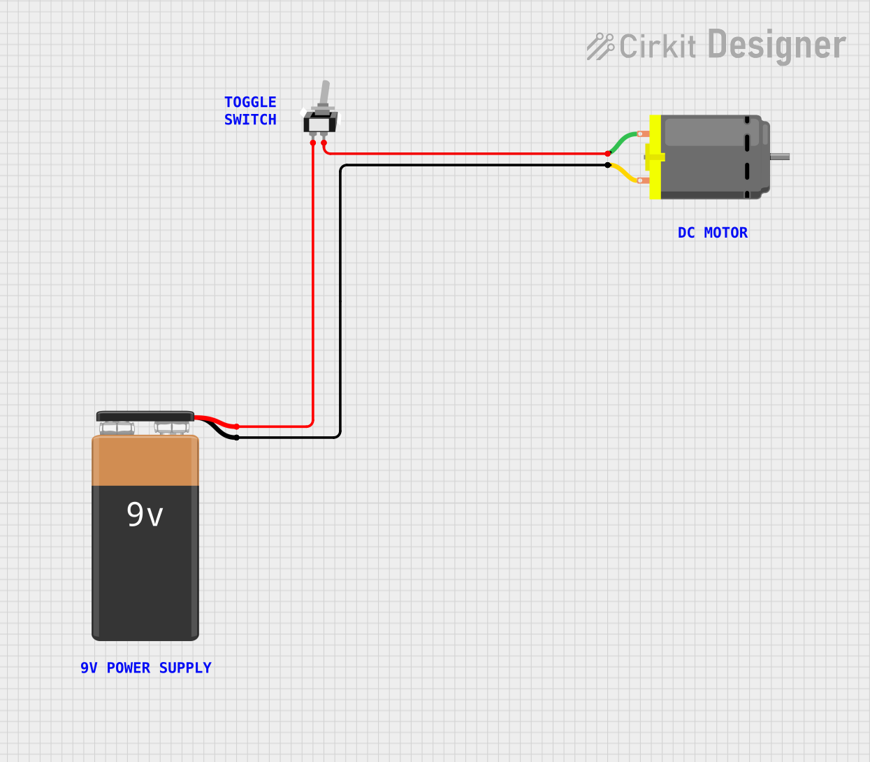
The circuit described by the provided inputs is a simple DC motor control circuit powered by a 9V battery. The circuit includes a single-pole single-throw (SPST) toggle switch to control the power supplied to the DC motor. When the switch is in the closed position, the motor is powered and should operate. There are no microcontrollers or complex electronics involved, making this a straightforward circuit suitable for basic on/off motor control applications.
Component List
DC Motor
- Description: A standard DC motor that converts electrical energy into mechanical rotation.
- Pins:
- pin 1: Motor positive supply
- pin 2: Motor negative supply
9V Battery
- Description: A 9-volt battery that provides the power source for the circuit.
- Pins:
- - : Negative terminal
- + : Positive terminal
Toggle Switch SPST
- Description: A single-pole single-throw toggle switch used to control the power to the motor.
- Pins:
- L1: Input from the battery's positive terminal
- COM: Output to the motor's positive supply
Comments
- Description: Placeholder components that may represent annotations or notes in the circuit design. These components do not have electrical functionality and are not physically present in the circuit.
Wiring Details
DC Motor
- pin 1 is connected to the COM pin of the Toggle Switch SPST.
- pin 2 is connected to the negative terminal (-) of the 9V Battery.
9V Battery
- The positive terminal (+) is connected to the L1 pin of the Toggle Switch SPST.
- The negative terminal (-) is connected to pin 2 of the DC Motor.
Toggle Switch SPST
- The L1 pin is connected to the positive terminal (+) of the 9V Battery.
- The COM pin is connected to pin 1 of the DC Motor.
Documented Code
There is no embedded code provided for this circuit as it does not include any programmable components or microcontrollers. The operation of the circuit is purely electrical and mechanical, controlled by the physical position of the toggle switch.